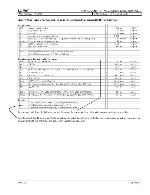
BC MoT SUPPLEMENT TO TAC GEOMETRIC DESIGN GUIDE MoT Section 1050 TAC Section Not Applicable Spreadsheet/Calculator Method The Spreadsheet/Calculator Method provides a detailed estimate <strong>of</strong> the inlet spacings for different crossfall and longitudinal grade combinations. This method is useful for low grades when using varying design ponding widths and optimizing inlet spacings. The model requires the following design input: SW y 0 s y s x n i width C w w is the paved shoulder width, m is the design depth <strong>of</strong> flow (for median), m is the longitudinal grade, m/m is the crossfall, m/m is the Manning’s roughness coefficient is the rainfall intensity for t c equal to 5 minutes, 5 year return period, mm/hr is the effective width <strong>of</strong> contributing area, m is the width weighted run<strong>of</strong>f coefficient is the inlet catchment width, m The model will calculate the following values: PW is the design ponding width, m y 0 is the maximum depth <strong>of</strong> gutter flow (for pavement), m R s is the crossfall-longitudinal grade ratio, m w eff is the effective inlet catchment width, m v is the gutter flow velocity, m/s Q 0 is the gutter flow, m 3 /s y over is the maximum depth <strong>of</strong> flow outside the catchment width, m Q over is the overflow, m 3 /s Q int is the intercepted flow, m 3 /s Eff is the inlet efficiency, % CB one is the initial inlet spacing, m CB two is the consecutive inlet spacing, m Grates/Spillways on a Crest Vertical Curve On vertical curves, the longitudinal grades near the crest are gradually reduced to zero and will result in closely spaced inlets. To increase the drainage capacity <strong>of</strong> the gutter, it might be possible to increase the crossfall (typically from 2% to 3%) at the crest. The crossfall transition should be long enough and far enough from the crest so as not to adversely affect the longitudinal slope <strong>of</strong> the gutter. Cross-Over Flow Particular attention should be paid to situations where rapid changes in grade and crossfall occur. Sag vertical curve and spiral combinations may experience channelized gutter flow which can leave one side <strong>of</strong> the pavement and cross-over to the other side. Careful attention must be paid to inlet spacings within the runout zone to minimize the bypass or cross-over flow. Since the inlet spacing methodologies presented in Section 1050.06 assume a certain degree <strong>of</strong> bypass flow, it is recommended that the last two inlets upslope <strong>of</strong> the Tangent to Spiral point should only be half the distance given by the design methodologies. Crest vertical curve and spiral combinations generally will not experience this type <strong>of</strong> channelized cross-over flow. Bridge Approaches The drainage for bridge decks is usually designed to only accommodate the bridge surface with no allowance for run<strong>of</strong>f from the approach roads. To avoid flow onto the bridge deck, the spacing <strong>of</strong> the last two catchbasins upslope <strong>of</strong> the bridge should only be half the distance given by the design methodologies. The last catchbasin should be as near to the end <strong>of</strong> the bridge as practicable. For detailed Spreadsheet/Calculator Method calculations, refer to Figures 1050.F to H. Grates/Spillways in a Sag Vertical Curve Twin catchbasins or a spillway should be placed in a sag vertical curve to maximize the open area. To prevent excess ponding, the distance to the next inlet should not exceed 100 m. Quite <strong>of</strong>ten in a vertical sag situation on higher fills, two separate drainage inlets are placed in close proximity to each other. The intent <strong>of</strong> this measure is to provide additional drainage capacity in the event that if one <strong>of</strong> the inlets becomes plugged, slope failure will not occur. Page 1050-6 June, 2007
BC MoT SUPPLEMENT TO TAC GEOMETRIC DESIGN GUIDE MoT Section 1050 TAC Section Not Applicable Figure 1050.F Sample Spreadsheet - Spacing for Depressed/Undepressed BC Bicycle Safe Grate Design Input SW = paved shoulder width = 1.2 m