1000 Hydraulics Chapter - Ministry of Transportation
1000 Hydraulics Chapter - Ministry of Transportation
1000 Hydraulics Chapter - Ministry of Transportation

You also want an ePaper? Increase the reach of your titles
YUMPU automatically turns print PDFs into web optimized ePapers that Google loves.
BC MoT<br />
SUPPLEMENT TO TAC GEOMETRIC DESIGN GUIDE<br />
MoT Section 1040 TAC Section Not Applicable<br />
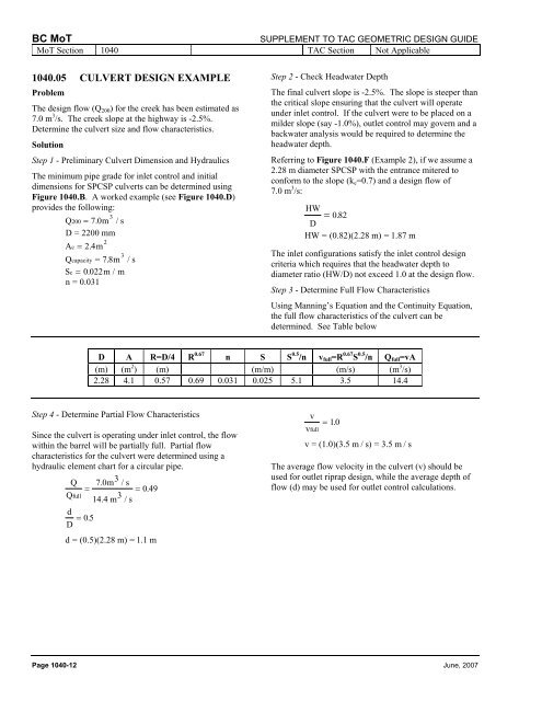
1040.05 CULVERT DESIGN EXAMPLE<br />
Problem<br />
The design flow (Q 200 ) for the creek has been estimated as<br />
7.0 m 3 /s. The creek slope at the highway is -2.5%.<br />
Determine the culvert size and flow characteristics.<br />
Solution<br />
Step 1 - Preliminary Culvert Dimension and <strong>Hydraulics</strong><br />
The minimum pipe grade for inlet control and initial<br />
dimensions for SPCSP culverts can be determined using<br />
Figure 1040.B. A worked example (see Figure 1040.D)<br />
provides the following:<br />
3<br />
Q200<br />
= 7.0 m / s<br />
D = 2200 mm<br />
2<br />
Ac<br />
= 2.4 m<br />
3<br />
Q capacity = 7. 8 m / s<br />
Sc = 0022 . m / m<br />
n = 0.031<br />
Step 2 - Check Headwater Depth<br />
The final culvert slope is -2.5%. The slope is steeper than<br />
the critical slope ensuring that the culvert will operate<br />
under inlet control. If the culvert were to be placed on a<br />
milder slope (say -1.0%), outlet control may govern and a<br />
backwater analysis would be required to determine the<br />
headwater depth.<br />
Referring to Figure 1040.F (Example 2), if we assume a<br />
2.28 m diameter SPCSP with the entrance mitered to<br />
conform to the slope (k e =0.7) and a design flow <strong>of</strong><br />
7.0 m 3 /s:<br />
HW<br />
=<br />
D 082 .<br />
HW = (0.82)(2.28 m) = 1.87 m<br />
The inlet configurations satisfy the inlet control design<br />
criteria which requires that the headwater depth to<br />
diameter ratio (HW/D) not exceed 1.0 at the design flow.<br />
Step 3 - Determine Full Flow Characteristics<br />
Using Manning’s Equation and the Continuity Equation,<br />
the full flow characteristics <strong>of</strong> the culvert can be<br />
determined. See Table below<br />
D A R=D/4 R 0.67 n S S 0.5 /n v full =R 0.67 S 0.5 /n Q full =vA<br />
(m) (m 2 ) (m) (m/m) (m/s) (m 3 /s)<br />
2.28 4.1 0.57 0.69 0.031 0.025 5.1 3.5 14.4<br />
Step 4 - Determine Partial Flow Characteristics<br />
Since the culvert is operating under inlet control, the flow<br />
within the barrel will be partially full. Partial flow<br />
characteristics for the culvert were determined using a<br />
hydraulic element chart for a circular pipe.<br />
Q 7.0m 3 / s<br />
=<br />
Qfull<br />
14.4 m 3 = 049 .<br />
/ s<br />
d<br />
D = 05 .<br />
d = (0.5)(2.28 m) = 1.1 m<br />
v<br />
vfull<br />
= 10 .<br />
v = (1.0)(3.5 m / s) = 3.5 m / s<br />
The average flow velocity in the culvert (v) should be<br />
used for outlet riprap design, while the average depth <strong>of</strong><br />
flow (d) may be used for outlet control calculations.<br />
Page 1040-12 June, 2007