

KM1301SAH-E Service Manual - Hoshizaki
KM1301SAH-E Service Manual - Hoshizaki
KM1301SAH-E Service Manual - Hoshizaki

Create successful ePaper yourself
Turn your PDF publications into a flip-book with our unique Google optimized e-Paper software.
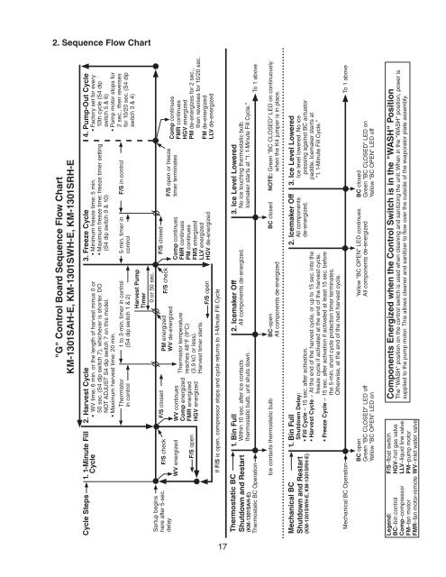
2. Sequence Flow Chart<br />
"G" Control Board Sequence Flow Chart<br />
KM-1301SAH-E, KM-1301SWH-E, KM-1301SRH-E<br />
Cycle Steps 1. 1-Minute Fill Cycle<br />
2. Harvest Cycle<br />
• WV time: 6 min. or the length of harvest minus 0 or<br />
50 sec. (S4 dip switch 7), whichever is shorter. DO<br />
NOT ADJUST S4 dip switch 7 on this model.<br />
• Maximum harvest time: 20 min.<br />
Sartup begins<br />
here after 5-sec.<br />
delay<br />
F/S check<br />
WV energized<br />
F/S open<br />
Thermistor<br />
in control<br />
F/S closed<br />
WV continues<br />
Comp energized<br />
FMR energized<br />
HGV energized<br />
1 to 3-min. timer in control<br />
(S4 dip switch 1 & 2)<br />
PM energized<br />
WV de-energized<br />
Thermistor temperature<br />
reaches 48°F (9°C)<br />
(3.9 kΩ or less).<br />
Harvest timer starts.<br />
Harvest Pump<br />
Timer<br />
F/S check<br />
F/S open<br />
If F/S is open, compressor stops and cycle returns to 1-Minute Fill Cycle<br />
0 or 50 sec.<br />
3. Freeze Cycle<br />
• Minimum freeze time: 5 min.<br />
• Maximum freeze time: freeze timer setting<br />
(S4 dip switch 9 & 10)<br />
5-min. timer in<br />
control<br />
F/S closed<br />
Comp continues<br />
FMR continues<br />
PM continues<br />
FMS energized<br />
LLV energized<br />
HGV de-energized<br />
F/S in control<br />
F/S open or freeze<br />
timer terminates<br />
4. Pump-Out Cycle<br />
• Factory set for every<br />
10th cycle (S4 dip<br />
switch 5 & 6)<br />
• Pump motor stops for<br />
2 sec., then reverses<br />
for 10/20 sec. (S4 dip<br />
switch 3 & 4)<br />
Comp continues<br />
FMR continues<br />
HGV energized<br />
PM de-energizes for 2 sec.,<br />
then reverses for 10/20 sec.<br />
FM de-energized<br />
LLV de-energized<br />
Thermostatic BC<br />
Shutdown and Restart<br />
(KM-1301SAH-E)<br />
Thermostatic BC Operation<br />
1. Bin Full<br />
Within 10 sec. after ice contacts<br />
thermostatic bulb, unit shuts down.<br />
2. Icemaker Off<br />
All components de-energized.<br />
3. Ice Level Lowered<br />
No ice touching thermostatic bulb.<br />
Icemaker starts at "1. 1-Minute Fill Cycle."<br />
To 1 above<br />
Ice contacts thermostatic bulb<br />
BC-open<br />
All components de-energized<br />
BC closed<br />
NOTE: Green "BC CLOSED" LED on continuously<br />
when the K4 jumper is in place.<br />
Mechanical BC<br />
Shutdown and Restart<br />
(KM-1301SWH-E, KM‐1301SRH-E)<br />
Mechanical BC Operation<br />
1. Bin Full<br />
Shutdown Delay:<br />
• Fill Cycle – 15 sec. after activation.<br />
• Harvest Cycle – At the end of the harvest cycle, or up to 15 sec. into the<br />
freeze cycle if activated at the end of the harvest cycle.<br />
• Freeze Cycle – 15 sec. after activation if activated at least 15 sec. before<br />
the 5-min. short cycle protection timer terminates.<br />
Otherwise, at the end of the next harvest cycle.<br />
2. Icemaker Off<br />
All components<br />
de-energized.<br />
3. Ice Level Lowered<br />
Ice level lowered. No ice<br />
pressing against BC actuator<br />
paddle. Icemaker starts at<br />
"1. 1-Minute Fill Cycle."<br />
To 1 above<br />
BC open<br />
Green "BC CLOSED" LED off<br />
Yellow "BC OPEN" LED on<br />
Yellow "BC OPEN" LED continues.<br />
All components de‐energized<br />
BC closed<br />
Green "BC CLOSED" LED on<br />
Yellow "BC OPEN" LED off<br />
Legend:<br />
BC–bin control<br />
Comp–compressor<br />
FM–fan motor<br />
FMR–fan motor-remote<br />
F/S–float switch<br />
HGV–hot gas valve<br />
LLV–liquid line valve<br />
PM–pump motor<br />
WV–inlet water valve<br />
Components Energized when the Control Switch is in the "WASH" Position<br />
The "WASH" position on the control switch is used when cleaning and sanitizing the unit. When in the "WASH" position, power is<br />
supplied to the pump motor. This allows cleaner and sanitizer to flow over the outside of the evaporator plate assembly.<br />
17


