Altivar 31 - Square D
Altivar 31 - Square D
Altivar 31 - Square D

You also want an ePaper? Increase the reach of your titles
YUMPU automatically turns print PDFs into web optimized ePapers that Google loves.
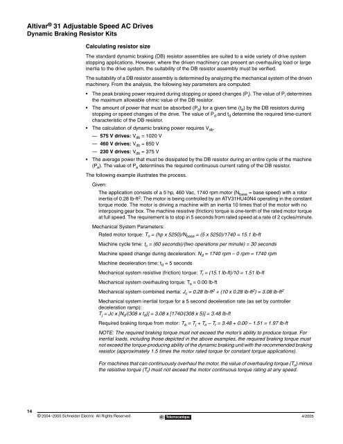
<strong>Altivar</strong> ® <strong>31</strong> Adjustable Speed AC Drives<br />
Dynamic Braking Resistor Kits<br />
14<br />
Calculating resistor size<br />
© 2004–2005 Schneider Electric All Rights Reserved<br />
The standard dynamic braking (DB) resistor assemblies are suited to a wide variety of drive system<br />
stopping applications. However, where the driven machinery can present an overhauling load or large<br />
inertia to the drive system, the suitability of the DB resistor assembly must be verified.<br />
The suitability of a DB resistor assembly is determined by analyzing the mechanical system of the driven<br />
machinery. From the analysis, the following key parameters are computed:<br />
The peak braking power required during stopping or speed changes (Pi ). The value of Pi determines<br />
the maximum allowable ohmic value of the DB resistor.<br />
The amount of power that must be absorbed (Pd ) for a given time (td ) by the DB resistors during<br />
stopping or speed changes of the drive. The value of Pd and td determine the required time-current<br />
characteristic of the DB resistor.<br />
The calculation of dynamic braking power requires Vdb .<br />
— 575 V drives: Vdb = 1020 V<br />
— 460 V drives: Vdb = 850 V<br />
— 230 V drives: Vdb = 375 V<br />
The average power that must be dissipated by the DB resistor during an entire cycle of the machine<br />
(Pa). The value of Pa determines the required continuous current rating of the DB resistor.<br />
The following example illustrates the process.<br />
Given:<br />
The application consists of a 5 hp, 460 Vac, 1740 rpm motor (Nbase = base speed) with a rotor<br />
inertia of 0.28 lb-ft2 . The motor is being controlled by an ATV<strong>31</strong>HU40N4 operating in the constant<br />
torque mode. The motor is driving a machine with an inertia 10 times that of the motor with no<br />
interposing gear box. The machine resistive (friction) torque is one-tenth of the rated motor torque<br />
at full speed. The requirement is to stop in 5 seconds from rated speed at a rate of 2 cycles/minute.<br />
Mechanical System Parameters:<br />
Rated motor torque: Tn = (hp x 5250)/Nbase = (5 x 5250)/1740 = 15.1 lb-ft<br />
Machine cycle time: t c = (60 seconds)/(two operations per minute) = 30 seconds<br />
Machine speed change during deceleration: N d = 1740 rpm – 0 rpm = 1740 rpm<br />
Machine deceleration time: t d = 5 seconds<br />
Mechanical system resistive (friction) torque: T r = (15.1 lb-ft)/10 = 1.51 lb-ft<br />
Mechanical system overhauling torque: T o = 0.00 lb-ft<br />
Mechanical system combined inertia: J c = 0.28 lb-ft 2 + (10 x 0.28 lb-ft 2 ) = 3.08 lb-ft 2<br />
Mechanical system inertial torque for a 5 second deceleration rate (as set by controller<br />
deceleration ramp):<br />
T j = Jc x [N d/(308 x t d)] = 3.08 x [1740/(308 x 5)] = 3.48 lb-ft<br />
Required braking torque from motor: T b = T j + T o – T r = 3.48 + 0.00 – 1.51 = 1.97 lb-ft<br />
NOTE: The required braking torque must not exceed the motor’s ability to produce torque. For<br />
inertial loads, including those depicted in the above examples, the required braking torque must<br />
not exceed the torque-producing ability of the dynamic braking unit with the recommended braking<br />
resistor (approximately 1.5 times the motor rated torque for constant torque applications).<br />
For machines that can continuously overhaul the motor, the value of overhauling torque (T o ) minus<br />
the resistive torque (T r) must not exceed the motor continuous torque rating at any speed.<br />
4/2005