Altivar 31 - Square D
Altivar 31 - Square D
Altivar 31 - Square D

You also want an ePaper? Increase the reach of your titles
YUMPU automatically turns print PDFs into web optimized ePapers that Google loves.
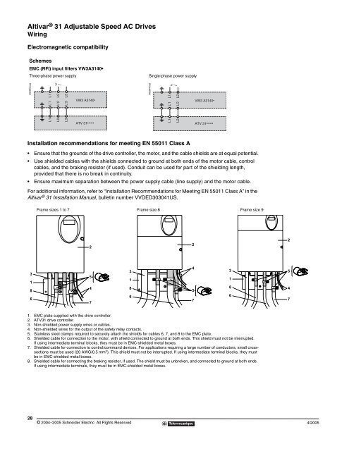
<strong>Altivar</strong> ® <strong>31</strong> Adjustable Speed AC Drives<br />
Wiring<br />
Electromagnetic compatibility<br />
Schemes<br />
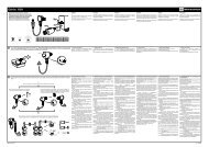
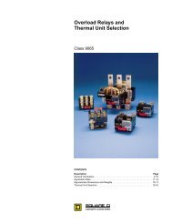
EMC (RFI) input filters VW3A<strong>31</strong>40<br />
Three-phase power supply Single-phase power supply<br />
562995.eps<br />
Installation recommendations for meeting EN 55011 Class A<br />
28<br />
Ensure that the grounds of the drive controller, the motor, and the cable shields are at equal potential.<br />
Use shielded cables with the shields connected to ground at both ends of the motor cable, control<br />
cables, and the braking resistor (if used). Conduit can be used for part of the shielding length,<br />
provided that there is no break in continuity.<br />
Ensure maximum separation between the power supply cable (line supply) and the motor cable.<br />
For additional information, refer to “Installation Recommendations for Meeting EN 55011 Class A” in the<br />
<strong>Altivar</strong> ® <strong>31</strong> Installation Manual, bulletin number VVDED303041US.<br />
3<br />
1<br />
8<br />
6<br />
L1<br />
L'1<br />
L1<br />
L2<br />
L'2<br />
L2<br />
L3<br />
L'3<br />
L3<br />
VW3 A<strong>31</strong>40<br />
ATV <strong>31</strong><br />
1. EMC plate supplied with the drive controller.<br />
2. ATV<strong>31</strong> drive controller.<br />
3. Non-shielded power supply wires or cables.<br />
4. Non-shielded wires for the output of the safety relay contacts.<br />
5. Stainless steel clamps required to securely attach the shields for cables 6, 7, and 8 to the EMC plate.<br />
6. Shielded cable for connection to the motor, with shield connected to ground at both ends. This shield must not be interrupted.<br />
If using intermediate terminal blocks, they must be in EMC-shielded metal boxes.<br />
7. Shielded cable for connection to control/command devices. For applications requiring a large number of conductors, small crosssections<br />
must be used (20 AWG/0.5 mm 2 ). This shield must not be interrupted. If using intermediate terminal blocks, they must<br />
be in EMC-shielded metal boxes.<br />
8. Shielded cable for connecting the braking resistor, if used. The shield must be unbroken, and connected to ground at both ends.<br />
If using intermediate terminals, they must be in EMC-shielded metal boxes.<br />
© 2004–2005 Schneider Electric All Rights Reserved<br />
2<br />
562994.eps<br />
L1<br />
L'1<br />
L1<br />
L2<br />
L'2<br />
L2<br />
VW3 A<strong>31</strong>40<br />
Frame sizes 1 to 7 Frame size 8 Frame size 9<br />
5<br />
4<br />
7<br />
3<br />
1<br />
8<br />
6<br />
2<br />
4<br />
5<br />
7<br />
ATV <strong>31</strong><br />
3<br />
1<br />
8<br />
6<br />
2<br />
5<br />
4<br />
7<br />
4/2005