Altivar 31 - Square D
Altivar 31 - Square D
Altivar 31 - Square D

You also want an ePaper? Increase the reach of your titles
YUMPU automatically turns print PDFs into web optimized ePapers that Google loves.
ATV<strong>31</strong> Wiring.eps<br />
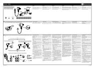
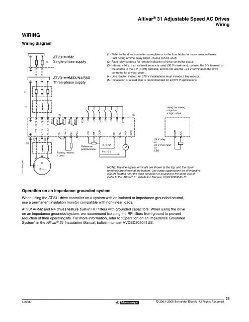
WIRING<br />
Wiring diagram<br />
(1)<br />
(4)<br />
(5)<br />
Operation on an impedance grounded system<br />
4/2005<br />
U1<br />
R / L1<br />
R / L1<br />
U / T1<br />
V1<br />
S / L2<br />
S / L2<br />
V / T2<br />
(1)<br />
W1<br />
M<br />
3 c<br />
T / L3<br />
R1A<br />
W / T3<br />
ATV<strong>31</strong> M2<br />
Single-phase supply<br />
ATV<strong>31</strong> M3X/N4/S6X<br />
Three-phase supply<br />
R1C<br />
(2)<br />
P0<br />
R1B<br />
PA / +<br />
R2A<br />
PB<br />
R2C<br />
Braking resistor,<br />
if used<br />
PC / -<br />
CLI<br />
LI1<br />
+10<br />
LI2<br />
AI1<br />
Reference<br />
potentiometer<br />
LI3<br />
COM<br />
<strong>Altivar</strong> ® <strong>31</strong> Adjustable Speed AC Drives<br />
Wiring<br />
When using the ATV<strong>31</strong> drive controller on a system with an isolated or impedance grounded neutral,<br />
use a permanent insulation monitor compatible with non-linear loads.<br />
LI4<br />
(1) Refer to the drive controller nameplate or to the fuse tables for recommended fuses.<br />
Fast acting or time delay Class J fuses can be used.<br />
(2) Fault relay contacts for remote indication of drive controller status.<br />
(3) Internal +24 V. If an external source is used (30 V maximum), connect the 0 V terminal of<br />
the source to the 0 V (COM) terminal, and do not use the +24 V terminal on the drive<br />
controller for any purpose.<br />
(4) Line reactor, if used. All 575 V installations must include a line reactor.<br />
(5) Installation of a load filter is recommended for all 575 V applications.<br />
ATV<strong>31</strong> M2 and N4 drives feature built-in RFI filters with grounded capacitors. When using the drive<br />
on an impedance grounded system, we recommend isolating the RFI filters from ground to prevent<br />
reduction of their operating life. For more information, refer to “Operation on an Impedance Grounded<br />
System” in the <strong>Altivar</strong> ® <strong>31</strong> Installation Manual, bulletin number VVDED303041US.<br />
LI5<br />
X–Y mA<br />
0 ± 10 V<br />
AI3<br />
LI6<br />
AI2<br />
24V<br />
AOV<br />
AOC<br />
(3)<br />
24 V relay<br />
or<br />
24 V PLC input<br />
or<br />
LED<br />
Using the analog<br />
output as<br />
a logic output<br />
NOTE: The line supply terminals are shown at the top, and the motor<br />
terminals are shown at the bottom. Use surge suppressors on all inductive<br />
circuits located near the drive controller or coupled to the same circuit.<br />
Refer to the <strong>Altivar</strong> ® <strong>31</strong> Installation Manual, VVDED303041US.<br />
COM<br />
A0C<br />
© 2004–2005 Schneider Electric All Rights Reserved<br />
25