Altivar 31 - Square D
Altivar 31 - Square D
Altivar 31 - Square D

You also want an ePaper? Increase the reach of your titles
YUMPU automatically turns print PDFs into web optimized ePapers that Google loves.
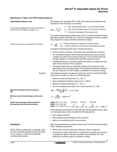
Mounting in a Type 12 or IP54 metal enclosure<br />
Calculating enclosure size<br />
For the power dissipated by the drive controllers at<br />
rated load, see the tables on pages 10–11.<br />
Contact the enclosure manufacturer for K factors.<br />
Maximum allowable thermal resistance,<br />
Rth<br />
Minimum useful heat exchange surface area,<br />
S<br />
Useful heat exchange surface area (S) of<br />
the proposed wall-mounted enclosure<br />
Ventilation<br />
NOTE: Where condensation is possible, keep<br />
the drive controller powered up when the motor<br />
is not running, or install thermostatically<br />
controlled strip heaters.<br />
4/2005<br />
<strong>Altivar</strong> ® <strong>31</strong> Adjustable Speed AC Drives<br />
Mounting<br />
The equation for calculating Rth (° C/W), the maximum allowable thermal<br />
resistance of the enclosure, is as follows:<br />
Ti – To Rth = ----------------<br />
P<br />
The useful heat exchange surface area, S (in 2 ), of a wall-mounted enclosure<br />
generally consists of the sides, top, and front. Calculate the minimum surface<br />
area required for a drive controller enclosure as follows:<br />
S<br />
K<br />
= ---------<br />
Rth<br />
Consider the following points when sizing the enclosure:<br />
Use only metal enclosures, since they have good thermal conduction.<br />
Do not install enclosures where external heat sources (such as direct<br />
sunlight) can add to the enclosure heat load. This procedure does not<br />
consider radiant or convected heat load from external sources.<br />
If additional devices are present inside the enclosure, consider the heat<br />
load of those devices in the calculation.<br />
The actual useful area for convection cooling of the enclosure varies<br />
depending on the mounting method. The mounting method must allow for<br />
free air movement over all surfaces considered for convection cooling.<br />
Example The following example calculates the enclosure size for an ATV<strong>31</strong>HU40N4<br />
(5 hp) drive mounted in a Type 12 or IP54 enclosure.<br />
Maximum external temperature: To = 25 ° C<br />
Power dissipated inside the enclosure: P = 150 W<br />
Maximum internal temperature: Ti = 40 ° C<br />
Thermal resistance per square inch of the enclosure: K = 186<br />
Rth<br />
Height: 28 in. (711 mm)<br />
Width: 24 in. (610 mm)<br />
Depth: 12 in. (305 mm)<br />
Ti = Max. internal ambient temp. (°C) around the controller<br />
To = Max. external ambient temp. (°C) around the enclosure<br />
P = Total power dissipated in the enclosure (W)<br />
K = Thermal resistance per square inch of the enclosure<br />
Rth = Thermal resistance of the enclosure (calculated previously)<br />
40 °C – 25 °C<br />
= ----------------------------------- = 0.115 °C/W<br />
150 W<br />
186<br />
S -------------- 1624.4 in.<br />
0.115<br />
2<br />
= =<br />
front area top area side area<br />
S ( 24 × 28)<br />
+ ( 24 × 12)<br />
+ 228 ( × 12)<br />
1632 in. 2<br />
= =<br />
If the selected enclosure does not provide the required surface area or does<br />
not meet application needs, consider the following options:<br />
Use a larger enclosure.<br />
Add a passive heat exchanger to the enclosure.<br />
Add an air conditioning unit to the enclosure.<br />
When mounting the drive controller inside a Type 12 or IP54 enclosure, follow<br />
these ventilation precautions:<br />
Observe the minimum clearance distances shown on page 29.<br />
If necessary, install a stirring fan to circulate the air inside the enclosure,<br />
to prevent hot spots in the drive controller and to distribute the heat<br />
uniformly to surfaces used for convection cooling.<br />
© 2004–2005 Schneider Electric All Rights Reserved<br />
<strong>31</strong>