Altivar 31 - Square D
Altivar 31 - Square D
Altivar 31 - Square D

You also want an ePaper? Increase the reach of your titles
YUMPU automatically turns print PDFs into web optimized ePapers that Google loves.
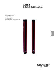
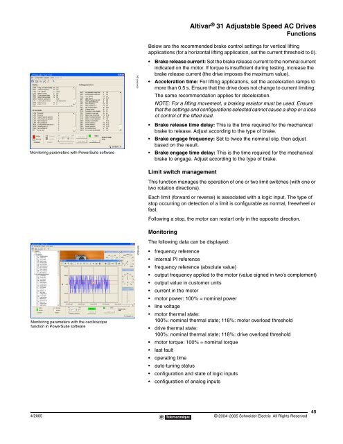
Monitoring parameters with PowerSuite software<br />
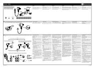
Monitoring parameters with the oscilloscope<br />
function in PowerSuite software<br />
operation.jpg<br />
scope.jpg<br />
<strong>Altivar</strong> ® <strong>31</strong> Adjustable Speed AC Drives<br />
Functions<br />
Below are the recommended brake control settings for vertical lifting<br />
applications (for a horizontal lifting application, set the current threshold to 0).<br />
Brake release current: Set the brake release current to the nominal current<br />
indicated on the motor. If torque is insufficient during testing, increase the<br />
brake release current (the drive imposes the maximum value).<br />
Acceleration time: For lifting applications, set the acceleration ramps to<br />
more than 0.5 s. Ensure that the drive does not change to current limiting.<br />
The same recommendation applies for deceleration.<br />
NOTE: For a lifting movement, a braking resistor must be used. Ensure<br />
that the settings and configurations selected cannot cause a drop or a loss<br />
of control of the lifted load.<br />
Brake release time delay: This is the time required for the mechanical<br />
brake to release. Adjust according to the type of brake.<br />
Brake engage frequency: Set to twice the nominal slip, then adjust<br />
based on the result.<br />
Brake engage time delay: This is the time required for the mechanical<br />
brake to engage. Adjust according to the type of brake.<br />
Limit switch management<br />
This function manages the operation of one or two limit switches (with one or<br />
two rotation directions).<br />
Each limit (forward or reverse) is associated with a logic input. The type of<br />
stop occurring on detection of a limit is configurable as normal, freewheel or<br />
fast.<br />
Following a stop, the motor can restart only in the opposite direction.<br />
Monitoring<br />
The following data can be displayed:<br />
frequency reference<br />
internal PI reference<br />
frequency reference (absolute value)<br />
output frequency applied to the motor (value signed in two’s complement)<br />
output value in customer units<br />
current in the motor<br />
motor power: 100% = nominal power<br />
line voltage<br />
motor thermal state:<br />
100%: nominal thermal state; 118%: motor overload threshold<br />
drive thermal state:<br />
100%: nominal thermal state; 118%: drive overload threshold<br />
motor torque: 100% = nominal torque<br />
last fault<br />
operating time<br />
auto-tuning status<br />
configuration and state of logic inputs<br />
configuration of analog inputs<br />
4/2005 © 2004–2005 Schneider Electric All Rights Reserved<br />
45