Altivar 31 - Square D
Altivar 31 - Square D
Altivar 31 - Square D

You also want an ePaper? Increase the reach of your titles
YUMPU automatically turns print PDFs into web optimized ePapers that Google loves.
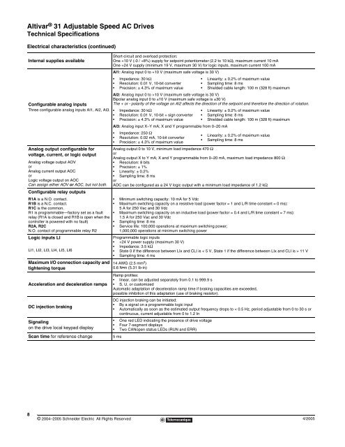
<strong>Altivar</strong> ® <strong>31</strong> Adjustable Speed AC Drives<br />
Technical Specifications<br />
Electrical characteristics (continued)<br />
Internal supplies available<br />
Configurable analog inputs<br />
Three configurable analog inputs AI1, AI2, AI3.<br />
Analog output configurable for<br />
voltage, current, or logic output<br />
Analog voltage output AOV<br />
or<br />
Analog current output AOC<br />
or<br />
Logic voltage output on AOC<br />
Can assign either AOV or AOC, but not both.<br />
Configurable relay outputs<br />
R1A is a N.O. contact.<br />
R1B is a N.C. contact.<br />
R1C is the common.<br />
R1 is programmable—factory set as a fault<br />
relay (R1A is closed and R1B is open when the<br />
controller is powered with no fault)<br />
R2A, R2C<br />
N.O. contact of programmable relay R2<br />
8<br />
© 2004–2005 Schneider Electric All Rights Reserved<br />
Short-circuit and overload protection:<br />
One +10 V (-0 / +8%) supply for setpoint potentiometer (2.2 to 10 kΩ), maximum current 10 mA<br />
One +24 V supply (minimum 19 V, maximum 30 V) for logic inputs, maximum current 100 mA<br />
AI1: Analog input 0 to +10 V (maximum safe voltage is 30 V)<br />
Impedance: 30 kΩ<br />
Resolution: 0.01 V, 10-bit converter<br />
Precision: ± 4.3% of maximum value<br />
Linearity: ± 0.2% of maximum value<br />
Sampling time: 8 ms<br />
Shielded cable length: 100 m (328 ft) maximum<br />
AI2: Analog input 0 to +10 V (maximum safe voltage is 30 V)<br />
Bipolar analog input 0 to ±10 V (maximum safe voltage is ±30 V)<br />
The + or - polarity of the voltage on AI2 affects the direction of the setpoint and therefore the direction of rotation.<br />
Impedance: 30 kΩ<br />
Resolution: 0.01 V, 10-bit + sign converter<br />
Precision: ± 4.3% of maximum value<br />
AI3: Analog input X–Y mA; X and Y programmable from 0–20 mA<br />
Impedance: 250 Ω<br />
Resolution: 0.02 mA, 10-bit converter<br />
Precision: ± 4.3% of maximum value<br />
Linearity: ± 0.2% of maximum value<br />
Sampling time: 8 ms<br />
Shielded cable length: 100 m (328 ft) maximum<br />
Linearity: ± 0.2% of maximum value<br />
Sampling time: 8 ms<br />
Analog output 0 to 10 V, minimum load impedance 470 Ω<br />
or<br />
Analog output X to Y mA; X and Y programmable from 0–20 mA, maximum load impedance 800 Ω:<br />
Resolution: 8 bits<br />
Precision: ± 1%<br />
Linearity: ± 0.2%<br />
Sampling time: 8 ms<br />
or<br />
AOC can be configured as a 24 V logic output with a minimum load impedance of 1.2 kΩ.<br />
Minimum switching capacity: 10 mA for 5 Vdc<br />
Maximum switching capacity on a resistive load (power factor = 1 and L/R time constant = 0 ms):<br />
5 A for 250 Vac and 30 Vdc<br />
Maximum switching capacity on an inductive load (power factor = 0.4 and L/R time constant = 7 ms):<br />
1.5 A for 250 Vac and 30 Vdc<br />
Sampling time: 8 ms<br />
Service life: 100,000 operations at maximum switching power;<br />
1,000,000 operations at minimum switching power<br />
Logic inputs LI Programmable logic inputs<br />
+24 V power supply (maximum 30 V)<br />
Impedance: 3.5 kΩ<br />
LI1, LI2, LI3, LI4, LI5, LI6<br />
State 0 if the difference between LIx and CLI is < 5 V, State 1 if the difference between LIx and CLI is > 11 V<br />
Sampling time: 4 ms<br />
Maximum I/O connection capacity and<br />
tightening torque<br />
Acceleration and deceleration ramps<br />
DC injection braking<br />
Signaling<br />
on the drive local keypad display<br />
Scan time for reference change 5 ms<br />
14 AWG (2.5 mm 2 )<br />
0.6 N m (5.<strong>31</strong> lb-in)<br />
Ramp profiles:<br />
linear, can be adjusted separately from 0.1 to 999.9 s<br />
S, U, or customized<br />
Automatic adaptation of deceleration ramp time if braking capacities are exceeded,<br />
possible inhibition of this adaptation (use of braking resistor).<br />
DC injection braking can be initiated:<br />
By a signal on a programmable logic input<br />
Automatically as soon as the estimated output frequency drops to < 0.5 Hz, period adjustable from 0 to 30 s or<br />
continuous, current adjustable from 0 to 1.2 In<br />
One red LED indicating the presence of drive voltage<br />
Four 7-segment displays<br />
Two CANopen status LEDs (RUN and ERR)<br />
4/2005