Altivar 31 - Square D
Altivar 31 - Square D
Altivar 31 - Square D

You also want an ePaper? Increase the reach of your titles
YUMPU automatically turns print PDFs into web optimized ePapers that Google loves.
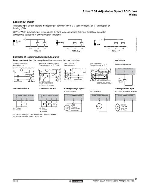
Logic input switch<br />
4/2005<br />
<strong>Altivar</strong> ® <strong>31</strong> Adjustable Speed AC Drives<br />
Wiring<br />
The logic input switch assigns the logic input common link to 0 V (Source logic), 24 V (Sink logic), or<br />
floating (CLI).<br />
NOTE: When the logic input is configured for Sink logic, grounding the input signals can result in<br />
unintended activation of drive controller functions.<br />
Source<br />
(1)<br />
Examples of recommended circuit diagrams<br />
Logic input switches (the heavy dashed line represents the drive controller) AOC output<br />
Source position (1)<br />
Internal supply<br />
+24<br />
Relay Contacts<br />
0V<br />
CLI LI1 LIx<br />
CLI at 0 V<br />
Source or Floating position<br />
External supply or PLC (2)<br />
Sink position<br />
Internal supply<br />
Floating position<br />
External supply or PLC<br />
Wired as logic output<br />
Two-wire control Three-wire control Analog voltage inputs Analog current input<br />
+ 24 V<br />
LI1<br />
LI1: Forward<br />
LIx: Reverse<br />
24 V Internal Source<br />
COM<br />
CLI<br />
LI1<br />
LIx<br />
ATV<strong>31</strong> control terminals<br />
LIx<br />
1) Factory setting for controllers other than ATV<strong>31</strong> A<br />
2) Jumper installed from COM to CLI.<br />
+24<br />
+24<br />
COM<br />
CLI<br />
PLC with either transistor<br />
outputs or relay contacts<br />
and its own internal supply<br />
+ 24 V<br />
24 V Internal Source<br />
LI1<br />
LIx<br />
ATV<strong>31</strong> control terminals<br />
LI1<br />
LI1: Stop<br />
LI2: Forward<br />
LIx: Reverse<br />
LI2<br />
LIx<br />
Floating<br />
CLI LI1 LIx<br />
CLI Floating<br />
+24<br />
LI1<br />
+24<br />
CLI<br />
COM<br />
LIx<br />
24 V Internal Source<br />
Relay Contacts<br />
+24<br />
LI1<br />
LIx<br />
CLI<br />
Sink<br />
± 10 V external ± 10 V external 0–20 mA, 4–20 mA, X–Y mA<br />
ATV<strong>31</strong> control terminals<br />
+ 10 V<br />
AI1<br />
Speed<br />
reference<br />
potentiometer<br />
2.2 to 10 kΩ<br />
0 V<br />
24V<br />
24 V Internal Source<br />
+24<br />
CLI LI1 LIx<br />
COM<br />
PLC with either transistor<br />
outputs or relay contacts<br />
and its own internal supply<br />
ATV<strong>31</strong> control terminals<br />
AI2<br />
± 10 V<br />
0 V<br />
CLI at 24 V ATV<strong>31</strong> Logic Input Switch.eps<br />
ATV<strong>31</strong> control terminals<br />
24 V<br />
relay<br />
10 mA<br />
AOC<br />
0 V<br />
ATV<strong>31</strong> control terminals<br />
AI3<br />
Source<br />
0–20 mA<br />
4–20 mA<br />
X–Y mA<br />
0 V<br />
© 2004–2005 Schneider Electric All Rights Reserved<br />
27