Altivar 31 - Square D
Altivar 31 - Square D
Altivar 31 - Square D

Create successful ePaper yourself
Turn your PDF publications into a flip-book with our unique Google optimized e-Paper software.
<strong>Altivar</strong> ® <strong>31</strong> Adjustable Speed AC Drives<br />
Dynamic Braking Resistor Kits<br />
DB resistor requirements:<br />
Peak braking power required to develop braking torque (Tb) when decelerating from a given speed:<br />
Pi = (Tb x Nbase )/7.04 = (1.97 x 1740)/7.04 = 487 W<br />
The braking power that must be absorbed for a time (t d) during a stop or speed change operation:<br />
P d = 0.5 x P i = 0.5 x 487 = 243 W for a period of t d seconds<br />
The average braking power that must be dissipated during a machine cycle:<br />
P a = P d x t d/t c = 243 x 5/30 = 40.5 W<br />
Capability of VW3A66711 DB resistor assembly for ATV<strong>31</strong>HU40N4 controller:<br />
Peak braking power that can be developed with the VW3A66711 DB resistor assembly with the<br />
controller configured for 460 Vac input line operation: P i = (V db) 2 /R db = (850 V) 2 /120 Ω = 6020 W<br />
The braking power that can be absorbed for t d (based on the DB resistor hot state current-time<br />
characteristic curve shown below):<br />
P d = R db x [(Multiple of I r at t d) x Ir] 2 = 120 Ω x (3.5 x 1.0) 2 = 1470 W<br />
Since R db limits the peak current that can be drawn from the drive controller DC bus, the value of<br />
[(Multiple of I r ) x I r ] must be limited to no greater than (√ P i /R db ).<br />
The average braking power that can be dissipated continuously:<br />
P a = R db x (I r ) 2 = 120 Ω x (1) 2 = 120 W<br />
For this example, the VW3A66711 DB resistor assembly will work as intended for the application.<br />
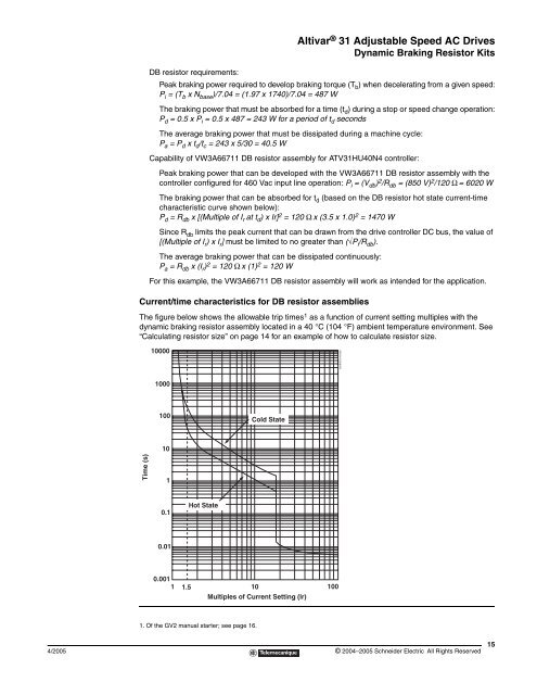
Current/time characteristics for DB resistor assemblies<br />
The figure below shows the allowable trip times 1 as a function of current setting multiples with the<br />
dynamic braking resistor assembly located in a 40 °C (104 °F) ambient temperature environment. See<br />
“Calculating resistor size” on page 14 for an example of how to calculate resistor size.<br />
Time (s)<br />
10000<br />
1000<br />
100<br />
10<br />
1<br />
0.1<br />
0.01<br />
Hot State<br />
0.001<br />
1 1.5 10<br />
Multiples of Current Setting (lr)<br />
100<br />
1. Of the GV2 manual starter; see page 16.<br />
Cold State<br />
4/2005 © 2004–2005 Schneider Electric All Rights Reserved<br />
DynBrkCurves.eps<br />
15