
Create successful ePaper yourself
Turn your PDF publications into a flip-book with our unique Google optimized e-Paper software.
2 Input Data<br />
The buckling length of a member can also be defined in a dialog box that you open by clicking<br />
the button shown on the left. In the table, you find the button below the upper table<br />
part on the right.<br />
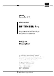
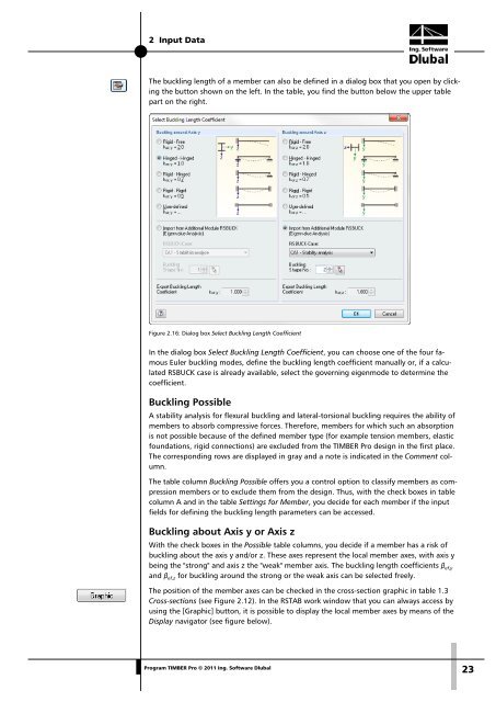
Figure 2.16: Dialog box Select Buckling Length Coefficient<br />
In the dialog box Select Buckling Length Coefficient, you can choose one of the four famous<br />
Euler buckling modes, define the buckling length coefficient manually or, if a calculated<br />
RSBUCK case is already available, select the governing eigenmode to determine the<br />
coefficient.<br />
Buckling Possible<br />
A stability analysis for flexural buckling and lateral-torsional buckling requires the ability of<br />
members to absorb compressive forces. Therefore, members for which such an absorption<br />
is not possible because of the defined member type (for example tension members, elastic<br />
foundations, rigid connections) are excluded from the <strong>TIMBER</strong> <strong>Pro</strong> design in the first place.<br />
The corresponding rows are displayed in gray and a note is indicated in the Comment column.<br />
The table column Buckling Possible offers you a control option to classify members as compression<br />
members or to exclude them from the design. Thus, with the check boxes in table<br />
column A and in the table Settings for Member, you decide for each member if the input<br />
fields for defining the buckling length parameters can be accessed.<br />
Buckling about Axis y or Axis z<br />
With the check boxes in the Possible table columns, you decide if a member has a risk of<br />
buckling about the axis y and/or z. These axes represent the local member axes, with axis y<br />
being the "strong" and axis z the "weak" member axis. The buckling length coefficients β ef,y<br />
and β ef,z for buckling around the strong or the weak axis can be selected freely.<br />
The position of the member axes can be checked in the cross-section graphic in table 1.3<br />
Cross-sections (see Figure 2.12). In the RSTAB work window that you can always access by<br />
using the [Graphic] button, it is possible to display the local member axes by means of the<br />
Display navigator (see figure below).<br />
<strong>Pro</strong>gram <strong>TIMBER</strong> <strong>Pro</strong> © 2011 Ing. <strong>Software</strong> <strong>Dlubal</strong><br />
23