TTDMâNMM and - California Detection Systems
TTDMâNMM and - California Detection Systems
TTDMâNMM and - California Detection Systems

You also want an ePaper? Increase the reach of your titles
YUMPU automatically turns print PDFs into web optimized ePapers that Google loves.
Service Events<br />
Introduction<br />
A TraceTek sensing circuit consists of two electrical loops (a diagram of the sensing circuit<br />
is shown in Appendix 3). The TTDM SIM module constantly monitors to see whether<br />
current is passing between the loops. When the system is normal, there is no current<br />
passing between the loops. When there is a leak on the system, the maximum current<br />
flows (just 270 µA; the sensing cable operates on low voltage <strong>and</strong> is safe to touch).<br />
If, however, the TTDM-SIM module detects a lower but significant level of current flow<br />
between the loops, it communicates with the NMM module to activate the Service alarm.<br />
A low-level current could indicate one or more of the following:<br />
• A very small leak (which may soon develop into a full leak alarm).<br />
• Heavy condensation or small spills (coffee, tea, etc.) on a sensing cable for water<br />
or aqueous solutions (TT1000 <strong>and</strong> TT3000).<br />
• Conductive material on a sensing cable for water or aqueous solutions. The material<br />
might be metal filings, concrete dust, flux, mastic, or other construction debris,<br />
or carbon-based dust from air-h<strong>and</strong>ling units, printers, or copiers.<br />
While it is recommended that service alarms be investigated, the operation of the system<br />
is not threatened; the TTDM-SIM <strong>and</strong> TTDM-NMM will continue to detect leaks.<br />
However, the accuracy of location may be affected in certain cases.<br />
The Service Alarm<br />
When the TTDM-NMM detects a condition requiring service (such as described<br />
above), it signals the event by taking the following actions:<br />
• Sounds an intermittent beep.<br />
• Illuminates the yellow Service LED.<br />
• Switches the service relay to alarm condition.<br />
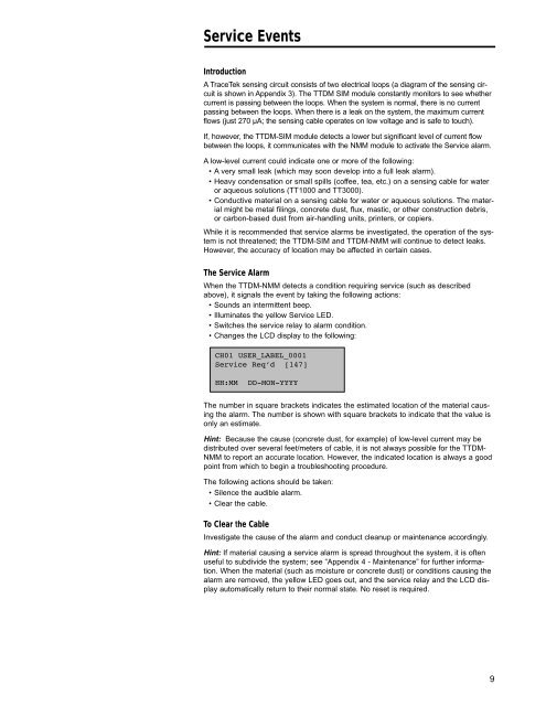
• Changes the LCD display to the following:<br />
CH01 USER_LABEL_0001<br />
Service ReqÕd [147]<br />
HH:MM DD-MON-YYYY<br />
The number in square brackets indicates the estimated location of the material causing<br />
the alarm. The number is shown with square brackets to indicate that the value is<br />
only an estimate.<br />
Hint: Because the cause (concrete dust, for example) of low-level current may be<br />
distributed over several feet/meters of cable, it is not always possible for the TTDM-<br />
NMM to report an accurate location. However, the indicated location is always a good<br />
point from which to begin a troubleshooting procedure.<br />
The following actions should be taken:<br />
• Silence the audible alarm.<br />
• Clear the cable.<br />
To Clear the Cable<br />
Investigate the cause of the alarm <strong>and</strong> conduct cleanup or maintenance accordingly.<br />
Hint: If material causing a service alarm is spread throughout the system, it is often<br />
useful to subdivide the system; see “Appendix 4 - Maintenance” for further information.<br />
When the material (such as moisture or concrete dust) or conditions causing the<br />
alarm are removed, the yellow LED goes out, <strong>and</strong> the service relay <strong>and</strong> the LCD display<br />
automatically return to their normal state. No reset is required.<br />
9