TTDMâNMM and - California Detection Systems
TTDMâNMM and - California Detection Systems
TTDMâNMM and - California Detection Systems

Create successful ePaper yourself
Turn your PDF publications into a flip-book with our unique Google optimized e-Paper software.
R<br />
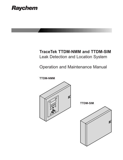
TraceTek TTDM-NMM <strong>and</strong> TTDM-SIM<br />
Leak <strong>Detection</strong> <strong>and</strong> Location System<br />
Operation <strong>and</strong> Maintenance Manual<br />
TTDM-NMM<br />
TTDM-SIM
Identifying TTDM-NMM <strong>and</strong> TTDM-SIM Features<br />
TTDM-NMM Network Master Module<br />
A<br />
Asterisk (*) preceding a feature denotes a<br />
TTDM-NMM feature not included in TTDM-SIM.<br />
R<br />
TraceTek<br />
TTDM<br />
External View [A]<br />
(TTDM-NMM only)<br />
1<br />
1<br />
*LCD display gives up-to-date information regarding<br />
the condition of the system.<br />
2<br />
3<br />
4<br />
Test<br />
Reset<br />
2<br />
*Icons <strong>and</strong> LEDs (light emitting diodes):<br />
Monitoring LED - green<br />
Service (Required) LED - yellow<br />
Leak LED - red<br />
Fault LED - red<br />
5<br />
6<br />
Esc<br />
Menu<br />
Enter<br />
3<br />
*(Self) Test key<br />
Can be used at any time to verify that the module<br />
is operating correctly. The module performs a<br />
series of self-diagnostic checks.<br />
B<br />
7<br />
(enlarged)<br />
8 9<br />
10<br />
4<br />
5<br />
*Silence key<br />
Used to silence audible alarms.<br />
*Reset key<br />
Used to reset the leak alarm relay after a leak has<br />
been cleared.<br />
4<br />
3<br />
11<br />
12<br />
13<br />
6<br />
*Menu keys<br />
The menu button provides access to various<br />
features that may be viewed <strong>and</strong>/or edited. The<br />
menus are navigated with the arrow keys along<br />
with the Esc (escape) <strong>and</strong> Enter keys.<br />
Internal View [B]<br />
7<br />
*User interface (UI) board<br />
14<br />
8<br />
9<br />
*4-20 mA board<br />
Sensor Interface (SI) board<br />
10<br />
Motherboard (MB)<br />
22 21<br />
20<br />
19<br />
18<br />
17<br />
16<br />
15<br />
11<br />
Power supply (PS-1, 2, or 24) board<br />
12<br />
Fuse (200 mA, 250 V)<br />
TTDM-SIM Sensor Interface Module<br />
B<br />
9 10<br />
13<br />
14<br />
Power cable terminal block<br />
Ground (earth) stud<br />
15<br />
*Fault relay cable plug <strong>and</strong> socket<br />
16<br />
*Leak relay cable plug <strong>and</strong> socket<br />
11<br />
12<br />
13<br />
14<br />
17<br />
18<br />
19<br />
20<br />
21<br />
22<br />
*Service relay cable plug <strong>and</strong> socket<br />
*4-20 mA port plug <strong>and</strong> socket<br />
*Plug <strong>and</strong> socket for RS-232/485 external communications<br />
serial port<br />
Sensing cable plug <strong>and</strong> socket<br />
RS-485 plug <strong>and</strong> socket for SIM network<br />
*Ribbon cable<br />
21<br />
20<br />
23<br />
*Volume adjustment<br />
24<br />
*LCD contrast adjustment
Contents<br />
Overview<br />
Identifying TTDM-NMM <strong>and</strong> TTDM-SIM Features . . . . . . . . . . . . . . Inside front cover<br />
Introduction . . . . . . . . . . . . . . . . . . . . . . . . . . . . . . . . . . . . . . . . . . . . . . . . . . . . . . 1<br />
Description of TraceTek Leak <strong>Detection</strong> System . . . . . . . . . . . . . . . . . . . . . . . . . . . . 2<br />
TraceTek Sensing Cables . . . . . . . . . . . . . . . . . . . . . . . . . . . . . . . . . . . . . . . . . . . 2<br />
Components of TraceTek Locating System . . . . . . . . . . . . . . . . . . . . . . . . . . . . . . .2<br />
Network of TraceTek TTDM-NMM <strong>and</strong> TTDM-SIM Modules . . . . . . . . . . . . . . . . . 3<br />
Connection of TraceTek TTDM-NMM System to Other Devices . . . . . . . . . . . . . . . 4<br />
Monitoring <strong>and</strong> Alarm Functions<br />
The TTDM-NMM System Display <strong>and</strong> Keypad . . . . . . . . . . . . . . . . . . . . . . . . . . . . . 5<br />
The Icons . . . . . . . . . . . . . . . . . . . . . . . . . . . . . . . . . . . . . . . . . . . . . . . . . . . . . . 5<br />
Current Event/Status Display (Normal Display Mode) . . . . . . . . . . . . . . . . . . . . . . 6<br />
The TTDM-NMM Keypad . . . . . . . . . . . . . . . . . . . . . . . . . . . . . . . . . . . . . . . . . . . 7<br />
Leak <strong>Detection</strong> <strong>and</strong> Location Events . . . . . . . . . . . . . . . . . . . . . . . . . . . . . . . . . . . . . 8<br />
Service Events . . . . . . . . . . . . . . . . . . . . . . . . . . . . . . . . . . . . . . . . . . . . . . . . . . . . 9<br />
Fault Events . . . . . . . . . . . . . . . . . . . . . . . . . . . . . . . . . . . . . . . . . . . . . . . . . . . . . 10<br />
Multiple Events . . . . . . . . . . . . . . . . . . . . . . . . . . . . . . . . . . . . . . . . . . . . . . . . . . . 11<br />
Features Accessed with Keypad<br />
Navigating the Menu Structure . . . . . . . . . . . . . . . . . . . . . . . . . . . . . . . . . . . . . . . 13<br />
Status of Individual SIM Channels . . . . . . . . . . . . . . . . . . . . . . . . . . . . . . . . . . . . . 14<br />
Modifying Settings for Individual SIM Channels . . . . . . . . . . . . . . . . . . . . . . . . . 15<br />
The Events History Log . . . . . . . . . . . . . . . . . . . . . . . . . . . . . . . . . . . . . . . . . . . . . 16<br />
System Status . . . . . . . . . . . . . . . . . . . . . . . . . . . . . . . . . . . . . . . . . . . . . . . . . . . . 17<br />
General Setup . . . . . . . . . . . . . . . . . . . . . . . . . . . . . . . . . . . . . . . . . . . . . . . . . . . . 18<br />
Leak Setup . . . . . . . . . . . . . . . . . . . . . . . . . . . . . . . . . . . . . . . . . . . . . . . . . . . . . . 19<br />
SIM Network . . . . . . . . . . . . . . . . . . . . . . . . . . . . . . . . . . . . . . . . . . . . . . . . . . . . . 20<br />
TTDM Network . . . . . . . . . . . . . . . . . . . . . . . . . . . . . . . . . . . . . . . . . . . . . . . . . . . 21<br />
Self Test . . . . . . . . . . . . . . . . . . . . . . . . . . . . . . . . . . . . . . . . . . . . . . . . . . . . . . . . 22<br />
Reference<br />
Appendix 1 – Menu Structure . . . . . . . . . . . . . . . . . . . . . . . . . . . . . . . . . . . . . . . . 23<br />
Appendix 2 – Events Glossary . . . . . . . . . . . . . . . . . . . . . . . . . . . . . . . . . . . . . . . . 24<br />
Appendix 3 – Technical Data on TraceTek Operation . . . . . . . . . . . . . . . . . . . . . . . . 25<br />
Appendix 4 – Maintenance . . . . . . . . . . . . . . . . . . . . . . . . . . . . . . . . . . . . . . . . . . 26<br />
Appendix 5 – Connection of TTDM-SIMs to RS-485 Network . . . . . . . . . . . . . . . . . 27<br />
Appendix 6 – Connection to Other Devices . . . . . . . . . . . . . . . . . . . . . . . . . . . . . . . 29<br />
Relays . . . . . . . . . . . . . . . . . . . . . . . . . . . . . . . . . . . . . . . . . . . . . . . . . . . . . . . 29<br />
4-20 mA Interface . . . . . . . . . . . . . . . . . . . . . . . . . . . . . . . . . . . . . . . . . . . . . . . 29<br />
Serial Port . . . . . . . . . . . . . . . . . . . . . . . . . . . . . . . . . . . . . . . . . . . . . . . . . . . . . 31<br />
Appendix 7 – Modbus Implementation . . . . . . . . . . . . . . . . . . . . . . . . . . . . . . . . . . 35<br />
Appendix 8 – TTDM-NMM Network Master Module Specifications . . . . . . . . . . . . . .46<br />
Appendix 9 – TTDM-SIM Sensor Interface Module Specifications . . . . . . . . . . . . . . .47<br />
Please read before use<br />
Please read these instructions carefully <strong>and</strong> keep in a safe place (preferably close to<br />
the TTDM-NMM module) for future reference.<br />
The instructions provided in this document should be followed carefully to ensure<br />
proper operation. If the equipment is used in a manner not specified by the manufacturer,<br />
the protection provided by the equipment may be impaired.<br />
Note: Software selections <strong>and</strong> key entries are highlighted in bold throughout this<br />
manual.
Introduction<br />
TTDM-NMM <strong>and</strong> TTDM-SIM modules are part of a TraceTek leak detection system;<br />
they link multiple areas into a single leak detection network. The modules have been<br />
specifically designed for use with TraceTek sensing cables (all TT1000, TT3000, <strong>and</strong><br />
TT5000 series sensing cables*). Each TTDM-SIM Sensor Interface Module (<strong>and</strong> the<br />
Sensor Interface board in the TTDM-NMM Network Master Module) can monitor up to<br />
5000 ft (1500 m) of sensing cable. A TTDM-NMM Network Master Module can monitor<br />
up to 15 TTDM-SIMs, allowing a maximum of 80,000 ft (24,000 m) of sensing<br />
cable in a single system. In addition, each TTDM-NMM has an assignable RS-485<br />
address, which allows a host system to monitor up to 31 TTDM-NMM leak detection<br />
systems.<br />
The TraceTek system can detect <strong>and</strong> locate the presence of liquid at any point along<br />
any of the sensing cables connected to the TTDM-NMM <strong>and</strong> TTDM-SIM modules.<br />
The modules also monitor the system for other alarm conditions:<br />
• Service required<br />
• Fault<br />
Each “event” (service, leak, or fault) is recorded in an Events History with the time<br />
<strong>and</strong> date of occurrence. This allows easy tracking of events. The TTDM-NMM module<br />
has a serial port that allows a host system to remotely access the events history <strong>and</strong><br />
all user settings.<br />
Preparation<br />
Before operation, installation instructions that accompany each module must be followed<br />
so that each module is properly:<br />
• Mounted.<br />
• Powered (wired <strong>and</strong> energized).<br />
• Connected to a TraceTek sensing cable with a TraceTek jumper or leader cable.<br />
• Interconnected with the other leak detection modules using RS-485 wiring.<br />
If these steps have not been taken, refer to the documents noted below to complete<br />
the installation. This literature can be obtained from the Raychem Fax-on-Dem<strong>and</strong><br />
service at (800) 329-4494; a voice prompt leads you through the process.<br />
• For the TTDM-NMM module, see the TTDM Installation Instructions (Raychem literature<br />
reference H55471).<br />
• For the TTDM-SIM module, see the TTDM-SIM Installation Instructions (Raychem<br />
literature reference H56314).<br />
• For interconnection of the modules with RS-485 wiring, see the TTDM-SIM<br />
Installation Instructions (Raychem literature reference H56314) <strong>and</strong> Appendix 5 of<br />
this operation <strong>and</strong> maintenance manual.<br />
Important: There should be a system map for each TTDM-SIM <strong>and</strong> the TTDM-NMM;<br />
the system map shows the sensing cable layout with reference l<strong>and</strong>marks throughout<br />
the system. The system map (an integral part of a TraceTek locating system) is often<br />
compiled when the leak detection system is commissioned. Ensure that a copy of<br />
each map is readily available near the TTDM-NMM module <strong>and</strong> (if the TTDM-NMM is<br />
connected to a building or facility management system) the host system as well.<br />
Notes<br />
• Throughout this manual, the examples shown use distances in feet.<br />
• Later versions of software may provide new features <strong>and</strong> change certain other<br />
details. This manual documents UI software version 1.00_.<br />
• For technical assistance, call (800) 553-1737 or (415) 361-4900.<br />
* TTDM-NMM <strong>and</strong> TTDM-SIM modules are also compatible with all long-line versions of<br />
the earlier sensing cables (TT100, TT300, <strong>and</strong> TT500 series).<br />
1
Description of TraceTek Leak <strong>Detection</strong> System<br />
TraceTek Sensing Cables<br />
The TraceTek leak detection system is based on sensing cables that detect liquid at<br />
any point along their length. Four types of TraceTek sensing cables are available to<br />
detect different types of liquids. Multiple types of sensing cables may be used in a single<br />
sensing circuit.<br />
TT1000 <strong>and</strong> TT3000<br />
Water <strong>and</strong> other conductive fluids<br />
TT5000 – fuels <strong>and</strong> oils<br />
TT5001 – organic solvents<br />
0.24 in.<br />
(6 mm)<br />
nominal<br />
Fluoropolymer<br />
carrier<br />
Sensing<br />
wires<br />
(black)<br />
0.28 in.<br />
(7 mm)<br />
Fluoropolymer<br />
braid<br />
Conductive<br />
polymer jacket<br />
Sensing<br />
wires<br />
(black)<br />
Components of TraceTek Locating System<br />
TraceTek leak detection is a versatile modular system, with interchangeable components<br />
that can be configured in many different ways. For more information on the<br />
products <strong>and</strong> systems available, consult the appropriate TraceTek product selection<br />
guide: Raychem document H53874 for water detection in commercial buildings,<br />
H55869 for industrial <strong>and</strong> environmental applications.<br />
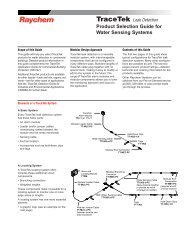
A TraceTek locating system provides distributed leak detection <strong>and</strong> location to monitor<br />
long lengths <strong>and</strong> wide areas. A TraceTek locating circuit consists of a TraceTek locating<br />
module, up to 5000 ft (1500 m) of sensing cable per module, <strong>and</strong> circuit components<br />
(leader cable, jumper cables, end terminations, weighted lengths, <strong>and</strong> branching<br />
connectors) with connectors that allow components of the system to plug together.<br />
TraceTek Alarm<br />
<strong>and</strong> Locating Module<br />
Modular leader cable<br />
Modular branching<br />
connector<br />
Sensing cable<br />
Weighted<br />
length<br />
Jumper<br />
cable<br />
Sensing cable<br />
Modular end<br />
termination<br />
Jumper cable<br />
Sensing cable<br />
Modular end<br />
termination<br />
The weighted length resistor simulates a 15-ft (5-m) length of sensing cable.<br />
Installed at the boundary between two areas, it allows the user to clearly identify the<br />
area where the leak has occurred.<br />
The branching connector enables the sensing cable to be branched. An end termination<br />
completes each branch. At the branching connector, the system first counts<br />
the sensing cable along the branch (middle connector), before it continues with the<br />
main run. Two built-in 15-ft (5-m) weighted-length resistors allow the user to clearly<br />
identify on which leg a leak has occurred near the branching connector.<br />
An important part of a TraceTek locating system is the system map, a sensing cable<br />
layout plan with actual distance readings. Thus, in case of an alarm, the location of<br />
the event can be determined quickly. The map should be placed near the Alarm <strong>and</strong><br />
Locating Module.<br />
2
Network of TraceTek TTDM-NMM <strong>and</strong> TTDM-SIM Modules<br />
The network of TTDM-NMM <strong>and</strong> TTDM-SIM modules adds capabilities beyond those<br />
of a st<strong>and</strong>-alone TraceTek TTDM single-channel alarm <strong>and</strong> locating module. Note that<br />
a separate operation <strong>and</strong> maintenance manual is available for the st<strong>and</strong>-alone single<br />
channel system (Raychem document H55472).<br />
In a network of TTDM-NMM <strong>and</strong> TTDM-SIM modules, each TTDM-SIM Sensor<br />
Interface Module (<strong>and</strong> the Sensor Interface board in the TTDM-NMM Network Master<br />
Module) can independently monitor up to 5000 ft (1500 m) of sensing cable. If liquid<br />
contacts sensing cable connected to a Sensor Interface Module, that module communicates<br />
the alarm condition to the TTDM-NMM Network Master Module, which signals<br />
an alarm, displays the distance to the leak, <strong>and</strong> records the event. The TTDM-NMM<br />
communicates with the SIMs over an RS-485 network (which uses a shielded, twisted<br />
pair); see Appendix 5 for wiring details. The RS-485 address for each SIM is assigned<br />
using the TTDM-NMM system software.<br />
A TTDM-NMM Network Master Module can monitor up to 15 TTDM-SIMs, allowing a<br />
maximum of 80,000 ft (24,000 m) of sensing cable in a single system. In addition,<br />
each TTDM-NMM has an assignable RS-485 address, which allows a host system to<br />
monitor up to 31 TTDM-NMM leak detection systems.<br />
TTDM-NMM<br />
Network<br />
Master<br />
Module<br />
RS-485<br />
2-wire<br />
network<br />
TTDM-SIM<br />
Sensor<br />
Interface<br />
Module<br />
3
Connection of TraceTek TTDM-NMM System to Other Devices<br />
All connections with external devices are made at the TTDM-NMM Network Master Module.<br />
The TTDM-NMM has three types of interface for communication with other systems:<br />
• Relays<br />
• 4-20 mA analog interface<br />
• Serial port<br />
See Appendix 6 for wiring <strong>and</strong> operating details.<br />
Relays<br />
The TTDM-NMM has three relays:<br />
• Service<br />
• Leak<br />
• Fault<br />
The relays are triggered by an alarm in any SIM channel. Each relay provides two<br />
Form-C relay contacts, with normally open <strong>and</strong> normally closed contacts both provided.<br />
4-20 mA Interface<br />
The TTDM-NMM is equipped with a 4-20 mA analog interface which can be used to<br />
communicate the status of a single channel. The module adjusts its current output<br />
based on whether an alarm condition exists <strong>and</strong> (when a leak is detected) the location<br />
of the leak. The output for leak location can be scaled to make full use of the<br />
4-20 mA range for the length of sensing cable connected to the assigned SIM channel.<br />
The SIM channel communicated over the analog interface is assigned using the<br />
TTDM-NMM system software; default is channel 01 (factory setting for the sensor<br />
interface board inside the TTDM-NMM itself).<br />
Serial Port<br />
The TTDM-NMM module has a serial port that can be configured for use either as an<br />
RS-232 or RS-485 transceiver. The factory default is RS-232 but can be changed to<br />
RS-485 using jumpers. Appendix 6 provides configuration <strong>and</strong> wiring details.<br />
Appendix 7 provides details on the TTDM-NMM Modbus implementation to facilitate<br />
integration with building <strong>and</strong> facility management systems.<br />
4
The TTDM-NMM System Display <strong>and</strong> Keypad<br />
The Icons<br />
The Icons represent the four states of the TTDM-NMM leak detection network.<br />
Green Yellow Red Red<br />
Monitoring<br />
Service<br />
Leak<br />
Fault<br />
Note: The Service, Leak, <strong>and</strong> Fault LEDs will illuminate if the condition exists on any<br />
SIM channel (i.e., the TTDM-NMM display uses OR logic). Therefore, multiple LEDs<br />
may be illuminated simultaneously to indicate multiple types of alarms, perhaps on<br />
different SIM channels.<br />
Monitoring<br />
This green LED indicates that the TTDM-NMM is monitoring the -SIM units attached<br />
to the TraceTek leak detection network.<br />
Service<br />
The TTDM-NMM is able to give advance warning of potential problems. This yellow<br />
Service LED illuminates to indicate that service is required on one of the sensing<br />
cables attached to the network. Note that the green LED remains illuminated; the unit<br />
continues to monitor for leaks during a Service alarm For further detail, see the<br />
“Service Events” section on page 9.<br />
Leak<br />
When liquid is detected in contact with a sensing cable, this red Leak LED illuminates. Note<br />
that the green LED remains illuminated; the unit continues to monitor for leaks <strong>and</strong> spills.<br />
This is covered more fully in the section “Leak <strong>Detection</strong> <strong>and</strong> Location Events” on page 8.<br />
Fault<br />
When the TTDM-NMM module detects a fault — either a cable fault or an electronics<br />
fault — it lights this red LED. After a fault on an individual SIM has been detected, the<br />
NMM module will, in most cases, continue to scan the remaining SIM units <strong>and</strong> their<br />
associated sensing cable. However, some fault conditions may disable multiple channels<br />
or even the entire system. The TTDM-NMM is unable to detect a leak on any<br />
channels affected by a fault, so always investigate the cause of a Fault condition<br />
immediately. For further information, see the “Fault Events” section on page 10.<br />
5
Current Event/Status Display (Normal Display Mode)<br />
CH01 USER_LABEL_0001<br />
CURR. EVENT/STATUS<br />
POSSIBLE USR ACTION<br />
HH:MM DD-MON-YYYY<br />
The LCD display is a backlit 4-line by 20-character display. If there is no activity for<br />
several minutes, the backlighting turns off, but turns back on when any key is<br />
pressed.<br />
Line 1<br />
identifies the channel currently displayed: shows the SIM channel number<br />
<strong>and</strong> a user-defined label up to 14 characters in length. For a new system,<br />
the user-defined label is blank.<br />
Line 2 indicates the current status of the SIM channel identified on Line 1,<br />
or<br />
in the case of Leak re-alarm, displays the initial Leak location of the SIM<br />
channel identified on Line 1.<br />
Line 3<br />
Line 4<br />
may advise action or provide special instructions,<br />
or<br />
in the case of Leak re-alarm, indicates the current status of the SIM channel<br />
identified on Line 1.<br />
displays the current time (in 24-hour format) <strong>and</strong> date; the colon blinks once<br />
a second,<br />
or<br />
in the case of Leak re-alarm may advise action or provide special instructions.<br />
Hint: The LCD contrast may be adjusted (feature<br />
cover).<br />
24<br />
in the diagram on the inside<br />
If no new alarm conditions exist, the LCD display scrolls through each connected SIM<br />
channel in sequence. The LCD presents the current event/status screen for each<br />
channel for about 4 seconds, then continues to the next available SIM channel number<br />
(<strong>and</strong> scrolls back to the first after the last channel).<br />
If the TTDM-NMM detects a new Service, Fault, or Leak event, it immediately jumps<br />
the display to the SIM channel affected, turns on the LCD back light, <strong>and</strong> pauses at<br />
that channel number for several minutes.<br />
Note: Use the left <strong>and</strong> right arrow keys to manually select the channel displayed.<br />
6
The TTDM-NMM Keypad<br />
TraceTek<br />
TTDM<br />
9<br />
1 Test<br />
Reset<br />
8<br />
2<br />
7<br />
3<br />
4<br />
Esc<br />
Menu<br />
Enter<br />
6<br />
5<br />
1. Test Triggers a limited series of self-tests; additional self-tests are<br />
accessed through the menu (see p. 22)<br />
2. Left/right arrows - In Current/Events Status display, manually select the<br />
channel displayed.<br />
- In menu selections, select digit to change.<br />
3. Menu Accesses menu of display <strong>and</strong> setup options<br />
(see “Navigating the Menu Structure” on page 13).<br />
4. Esc Goes back (up) one level in menu structure.<br />
Hint: Pressing Esc multiple times returns to the Current/Events<br />
Status display.<br />
5. Enter Selects a menu option.<br />
6. Down arrow - In Current/Events Status display, accesses detailed status<br />
information for the channel currently displayed (see page 14<br />
for detail).<br />
- In menu selections, scrolls down through displays <strong>and</strong> menu<br />
options.<br />
7. Up arrow Scrolls up in status displays <strong>and</strong> menu options.<br />
8. Reset Resets the Leak alarm relay (if <strong>and</strong> only if all leaks have been<br />
cleared); see next section for details.<br />
9. Silence Silences the audible alarm.<br />
7
Leak <strong>Detection</strong> <strong>and</strong> Location Events<br />
A Leak Alarm<br />
When liquid is detected by sensing cable in any channel, the following occur:<br />
• The audible alarm sounds.<br />
• The red Leak LED illuminates.<br />
• The display changes to show the channel <strong>and</strong> location of the leak.<br />
• The interfaces signal the event (Leak relay, 4-20 mA , <strong>and</strong> serial port)<br />
CH01 USER_LABEL_0001<br />
Leak 1662 ft<br />
HH:MM DD-MON-YYYY<br />
The following actions should be taken:<br />
• Silence the alarm (if necessary).<br />
• Locate the leak.<br />
• Clear the system.<br />
• Reset the leak relay. (This occurs automatically if Auto-Reset is enabled; see page<br />
19.)<br />
Hint: If audible alarms are not required, the module can be set to disable them<br />
(see “Audible Alarm” under “Leak Setup” on page 19).<br />
To Locate the Leak<br />
Using the channel number <strong>and</strong> location displayed by the TTDM-NMM, refer to the<br />
system map <strong>and</strong> determine where the leak was detected.<br />
To Clear the System<br />
Fix the leak <strong>and</strong> clean up the area affected. Then dry the sensing cable (in the case<br />
of TT1000 <strong>and</strong> TT3000) or replace the tripped section (TT5000 series). Once the sensing<br />
cable is clear, the module responds <strong>and</strong> the display changes:<br />
CH01 USER_LABEL_0001<br />
Leak Cleared<br />
Press reset<br />
HH:MM DD-MON-YYYY<br />
Notice that the red LED remains on. This is to indicate that the leak relay is still in the<br />
alarm state.<br />
To Reset the Leak Relay<br />
In order to reset the leak relay <strong>and</strong> return the module to the “SIM Normal” state, press<br />
the reset button. Before doing so, check that any external equipment controlled by the<br />
leak relay is ready to be reset.<br />
Once the Reset button is pressed, the relay returns to normal, the red Leak LED<br />
extinguishes, <strong>and</strong> the LCD returns to the normal display.<br />
Hint: If manual reset is not required, the TTDM-NMM can be set to auto-reset; see<br />
page 19.<br />
8
Service Events<br />
Introduction<br />
A TraceTek sensing circuit consists of two electrical loops (a diagram of the sensing circuit<br />
is shown in Appendix 3). The TTDM SIM module constantly monitors to see whether<br />
current is passing between the loops. When the system is normal, there is no current<br />
passing between the loops. When there is a leak on the system, the maximum current<br />
flows (just 270 µA; the sensing cable operates on low voltage <strong>and</strong> is safe to touch).<br />
If, however, the TTDM-SIM module detects a lower but significant level of current flow<br />
between the loops, it communicates with the NMM module to activate the Service alarm.<br />
A low-level current could indicate one or more of the following:<br />
• A very small leak (which may soon develop into a full leak alarm).<br />
• Heavy condensation or small spills (coffee, tea, etc.) on a sensing cable for water<br />
or aqueous solutions (TT1000 <strong>and</strong> TT3000).<br />
• Conductive material on a sensing cable for water or aqueous solutions. The material<br />
might be metal filings, concrete dust, flux, mastic, or other construction debris,<br />
or carbon-based dust from air-h<strong>and</strong>ling units, printers, or copiers.<br />
While it is recommended that service alarms be investigated, the operation of the system<br />
is not threatened; the TTDM-SIM <strong>and</strong> TTDM-NMM will continue to detect leaks.<br />
However, the accuracy of location may be affected in certain cases.<br />
The Service Alarm<br />
When the TTDM-NMM detects a condition requiring service (such as described<br />
above), it signals the event by taking the following actions:<br />
• Sounds an intermittent beep.<br />
• Illuminates the yellow Service LED.<br />
• Switches the service relay to alarm condition.<br />
• Changes the LCD display to the following:<br />
CH01 USER_LABEL_0001<br />
Service ReqÕd [147]<br />
HH:MM DD-MON-YYYY<br />
The number in square brackets indicates the estimated location of the material causing<br />
the alarm. The number is shown with square brackets to indicate that the value is<br />
only an estimate.<br />
Hint: Because the cause (concrete dust, for example) of low-level current may be<br />
distributed over several feet/meters of cable, it is not always possible for the TTDM-<br />
NMM to report an accurate location. However, the indicated location is always a good<br />
point from which to begin a troubleshooting procedure.<br />
The following actions should be taken:<br />
• Silence the audible alarm.<br />
• Clear the cable.<br />
To Clear the Cable<br />
Investigate the cause of the alarm <strong>and</strong> conduct cleanup or maintenance accordingly.<br />
Hint: If material causing a service alarm is spread throughout the system, it is often<br />
useful to subdivide the system; see “Appendix 4 - Maintenance” for further information.<br />
When the material (such as moisture or concrete dust) or conditions causing the<br />
alarm are removed, the yellow LED goes out, <strong>and</strong> the service relay <strong>and</strong> the LCD display<br />
automatically return to their normal state. No reset is required.<br />
9
Fault Events<br />
Introduction<br />
Several conditions could lead to a fault alarm:<br />
• A cable is disconnected.<br />
• A cable is damaged.<br />
• A connection is damaged.<br />
• A specific SIM module is damaged.<br />
• Communication is lost between the NMM <strong>and</strong> one or more SIM modules.<br />
What the NMM Module Does<br />
The following shows how the alarm display would appear if the fault were caused by a<br />
broken or disconnected cable:<br />
CH01 USER_LABEL_0001<br />
Cable Break<br />
HH:MM DD-MON-YYYY<br />
The TTDM-NMM would display a different message for a different type of fault, such<br />
as a loop imbalance or loss of communication to a specific SIM module.<br />
When a fault condition is detected, the following occur:<br />
• An audible alarm sounds.<br />
• The red Fault LED illuminates.<br />
• The LCD displays a message appropriate to the fault condition.<br />
• The interfaces signal the event (Fault relay, 4-20 mA , <strong>and</strong> serial port).<br />
To Remedy the Problem<br />
Find the problem <strong>and</strong> rectify. This may mean reconnecting the cable, or finding the<br />
damaged section <strong>and</strong> replacing it. If the cause of the fault is not obvious by visual<br />
inspection, it is often useful to subdivide the system <strong>and</strong> test individual sections with a<br />
TraceTek Portable Test Box.<br />
As soon as the fault is rectified, the relay, LED, <strong>and</strong> LCD display return to their normal<br />
state.<br />
10
Multiple Events<br />
Simultaneous Events on Different SIM Channels<br />
The TTDM-NMM is capable of monitoring as many as 16 sensing circuits (using 15<br />
external SIM modules plus its own internal sensor interface card). Each SIM operates<br />
independently of other SIMs in the leak detection network. The TTDM-NMM tracks<br />
information for all SIM channels <strong>and</strong> is capable of h<strong>and</strong>ling multiple events that occur<br />
in the same time frame. Any new event takes precedence on the LCD display. The<br />
LCD display will pause temporarily on the most recent event, giving the local operator<br />
time to read the LCD message <strong>and</strong> take action. After pausing several minutes on the<br />
most recent event, the TTDM-NMM display resumes automatic scrolling through each<br />
connected SIM channel.<br />
At any time, the operator may manually select a channel by using the left or right<br />
arrow keys. When a channel has been selected manually, the display pauses on the<br />
selected channel for several minutes before scrolling resumes.<br />
Multiple Events on a Single SIM Channel<br />
In some circumstances, multiple events may occur on a single SIM channel. The system<br />
continues to monitor during Service <strong>and</strong> Leak alarms, ensuring that the installation<br />
provides full-time protection. The TTDM-NMM stores all events in memory, <strong>and</strong> in<br />
addition updates the display based on the sequence of events in a SIM channel.<br />
Moving Leak<br />
The TTDM will re-alarm when the leak moves more than the re-alarm distance, for<br />
which the default is 5 ft (1.5 m). The audible alarm will sound, the third line of the<br />
LCD will change, <strong>and</strong> a new event will be added to the Events History.<br />
Example:<br />
Suppose a leak is detected at 370 feet:<br />
CH01 USER_LABEL_0001<br />
Leak 370 ft<br />
HH:MM DD-MON-YYYY<br />
Before the problem can be dealt with, the leak spreads. Once the module has<br />
detected significant movement (that is, greater than the re-alarm distance, a Leak setting<br />
described on page 19), the NMM module goes into alarm once again:<br />
CH01 USER_LABEL_0001<br />
Leak 370 ft<br />
Re-Alarm 365 ft<br />
HH:MM DD-MON-YYYY<br />
The LCD now displays:<br />
• the first leak on the second line <strong>and</strong><br />
• the most recent alarm on the third line.<br />
The first leak recorded on the SIM channel is likely to be close to the source of the leak.<br />
The most recent leak shows the current “electrical center” of the liquid (essentially a<br />
weighted average). If the Re-Alarm number is close to the first (as in the example<br />
above), it is likely that the leak has spread.<br />
11
Should the leak continue to spread, the TTDM would re-alarm again; the second line<br />
is updated again:<br />
CH01 USER_LABEL_0001<br />
Leak 370 ft<br />
Re-Alarm 360 ft<br />
HH:MM DD-MON-YYYY<br />
Hint: Use the Events History to track the events between the “first leak” <strong>and</strong> the “most<br />
recent event.” See “The Events History Log” section on page 16.<br />
Additional Leak<br />
If liquid contacts sensing cable in a SIM channel away from the initial leak, the module<br />
will re-alarm. If the location is distant from the last alarm, the TTDM shows a location<br />
in square brackets:<br />
CH01 USER_LABEL_0001<br />
Leak 370 ft<br />
Re-Alarm [205]<br />
HH:MM DD-MON-YYYY<br />
Brackets indicate that the value shown requires interpretation; when an additional<br />
leak occurs, the value represents the “electrical center” of the leaks.<br />
Service-to-Leak Alarm<br />
Although the TTDM-NMM <strong>and</strong> -SIM system can continue to monitor a channel when a<br />
Service Required alarm is in effect, the accuracy of location may be impaired.<br />
Example:<br />
CH01 USER_LABEL_0001<br />
Service ReqÕd [257]<br />
HH:MM DD-MON-YYYY<br />
If sensing cable on that SIM channel detects a full-fledged leak before service<br />
is performed, the NMM displays a new leak alarm. If the location measured is<br />
nearly the same as the earlier Service Required alarm, the display would<br />
appear as below:<br />
Leak at same location as Service Req’d<br />
CH01 USER_LABEL_0001<br />
Leak 257 ft<br />
HH:MM DD-MON-YYYY<br />
If the leak location is different from the earlier Service Required alarm, the<br />
NMM shows a slightly different display:<br />
Leak at different location from Service Req’d<br />
CH01 USER_LABEL_0001<br />
Leak [190]<br />
HH:MM DD-MON-YYYY<br />
The TTDM-NMM indicates the uncertainty about the leak location (due to the<br />
prior Service Required alarm condition) by showing the location in brackets.<br />
12
Navigating the Menu Structure<br />
Please refer to “Appendix 1 - Menu Structure” for an overview of the menu structure,<br />
<strong>and</strong> refer to the diagram on page 7 to locate the menu keys shown below:<br />
Menu<br />
Esc<br />
Enter<br />
From the Current Event/Status display:<br />
Press the down arrow key to access detailed status information for the channel<br />
currently displayed (described in detail on next page).<br />
Press the left <strong>and</strong> right arrow keys to manually select the channel displayed.<br />
Press the Menu key to access the many display <strong>and</strong> setup features in this section.<br />
Use up <strong>and</strong> down arrow keys to scroll through menu options <strong>and</strong> status displays.<br />
Use the left <strong>and</strong> right arrow keys to select individual characters.<br />
Press Enter to make a selection or go one level deeper into the menu structure.<br />
Press Esc to go back (up) one level in the menu structure.<br />
Note: If the unit is left in a menu display with no key presses for roughly 30 minutes,<br />
it automatically returns to the Current Event/Status display.<br />
The Scroll Bar<br />
The scroll bar (see example below) indicates that there is more information offscreen;<br />
an arrow indicates the direction of further information.<br />
Main Menu<br />
Event History<br />
System Status<br />
General Setup<br />
Menu Options<br />
The following are the options presented at the Main Menu level:<br />
• Event History<br />
• System Status<br />
• General Setup<br />
• Leak Setup<br />
• SIM Network<br />
• TTDM Network<br />
• Self-Test<br />
Entering a Password<br />
When a user attempts to change a restricted setting, the TTDM-NMM displays a<br />
password prompt. The factory default password is 0010 (to change the password, see<br />
page 18). To enter the password, proceed as follows:<br />
• Use left/right arrow keys to move to each digit.<br />
• Use the up/down arrows to increase/decrease the number.<br />
• Press Enter when complete.<br />
Note: Once the password is entered, it remains in effect (allowing access) until exit<br />
from the main menu to the normal display mode, or until there has been no keypad<br />
activity for 30 minutes.<br />
13
Status of Individual SIM Channels<br />
The NMM offers access to detailed real-time status information for each SIM channel.<br />
The status display for an individual SIM channel is accessed from the Current<br />
Event/Status display (the normal display mode):<br />
• If in a menu, press Esc one or more times to return the display to the normal display<br />
mode.<br />
• Use the left or right arrow keys to select the SIM channel of interest.<br />
• Press the down arrow to access the detailed status information (as shown below)<br />
for the selected channel.<br />
SIM Status:<br />
SIM Address 7<br />
{SIM status}<br />
ID User_Label_07<br />
TestLength 1690 ft<br />
Location ----- ft<br />
Current 0 µA<br />
R S-to-S ----- k½<br />
R RG Loop 6593 ½<br />
R YB Loop 6591 ½<br />
R Loc ----- ½<br />
NewLeakRes 100 ½<br />
BarrierRes 0 ½<br />
SI Version 0.27<br />
SI PID 1<br />
SI Comm 100 %<br />
Mode 0<br />
SI Status 380<br />
Note: Only four lines are displayed at one time. Arrows in the scroll bar indicate if<br />
other entries can be accessed with the up or down arrow keys. A description of each<br />
type of information available in SIM Status appears below:<br />
SIM Address<br />
SIM status<br />
ID<br />
Test Length<br />
Location<br />
Current<br />
Channel number for information in current display<br />
This is a variable field, which can contain any of the following<br />
text, depending on the state of that SIM channel:<br />
• SIM Normal<br />
• Leak<br />
• Re-alarm<br />
• Service Required<br />
• Fault (for specifics, see “Appendix 2 - Events History”)<br />
An alphanumeric label specified by the user (maximum 14 characters).<br />
The default value is User_Label_xx where xx is the SIM<br />
channel number.<br />
Total length of sensing cable attached to the selected SIM.<br />
The test length should be the same as that recorded when the<br />
channel was mapped. If the length is not the same, it may<br />
mean that the system was modified (sensing cable was<br />
removed or added).<br />
Note: The Test Length is typically about 1% longer than the<br />
physical or mapped length for the channel; this is normal.<br />
The current location — or electrical center — of the leak (or<br />
cause of a Service alarm). If the status is Normal, the<br />
Location entry is blank.<br />
This current (measured in µA) indicates the condition of the<br />
sensing cable. If a leak is detected in the channel, this rises to<br />
270 µA. In a clean, leak-free sensing circuit, the current<br />
should be 5 µA or less. If the current rises above 20 µA, service<br />
is recommended, as it may indicate the presence of<br />
contamination. To better underst<strong>and</strong> what the current means,<br />
see “Appendix 3 - Technical Data on TraceTek Operation,”<br />
which explains the TraceTek operating principle.<br />
14
R S-to-S<br />
R RG Loop,<br />
R YB Loop<br />
R Loc<br />
NewLeakRes<br />
BarrierRes<br />
SI Version<br />
SI PID<br />
SI Comm<br />
Mode<br />
SI Status<br />
This is the resistance from sensing wire to sensing wire (see<br />
Appendix 3 for detail). For a clean, leak-free sensing circuit,<br />
this resistance is in the M½ range. If liquid is detected, it<br />
drops to the k½ range or even lower. If the value is changing,<br />
it may indicate an event in progress.<br />
These are the resistances of the Red-Green <strong>and</strong> Yellow-Black<br />
loops in the TraceTek sensing circuit (see Appendix 3 for<br />
detail). If these values are significantly different from each<br />
other, it may indicate damage to a sensing cable or connector.<br />
This is the resistance measured along the black sensing wire<br />
to the location of the leak (see Appendix 3 for detail).<br />
This variable is used by the microprocessor to distinguish<br />
between a Re-alarm event <strong>and</strong> a new leak.<br />
This user setting is for the resistance of the zener safety<br />
barrier (if installed); the leak location algorithm subtracts this<br />
barrier resistance to “zero out” the barrier effect on the system<br />
map.<br />
This indicates the software version operating in the sensor<br />
interface microprocessor.<br />
This product code for the SI board is used by the NMM<br />
processor to recognize the type of SI card.<br />
This indicates the success rate (in percent) for communications<br />
between the NMM <strong>and</strong> the SIM channel selected. A<br />
value below 90% may indicate a faulty connection or damaged<br />
RS-485 cable.<br />
This index for the SI software location algorithm may assist<br />
factory personnel providing diagnostic support.<br />
This value indicates SIM solid state switch status <strong>and</strong> may<br />
assist factory personnel providing diagnostic support.<br />
Modifying Settings for Individual SIM Channels<br />
To change the alphanumeric tag for the selected SIM channel:<br />
• Select the appropriate SIM channel as described previously in this section.<br />
• Use the up <strong>and</strong> down arrows to select ID.<br />
• Press Enter.<br />
• Use the left <strong>and</strong> right arrows to select a character space to modify.<br />
• Use the Reset key to “tab” between Letters, Numbers, <strong>and</strong> blank.<br />
• Use the up <strong>and</strong> down arrows to cycle through all available characters until the<br />
desired character is displayed. There are numerous punctuation, currency,<br />
Katakana, <strong>and</strong> non-English alphabetical characters available. Going “up” or “down”<br />
cycles through all available characters.<br />
• Press Enter once label has been set up.<br />
To change the barrier resistance for the selected SIM channel:<br />
• Select the appropriate SIM channel as described previously in this section.<br />
• Use the up <strong>and</strong> down arrows to select BarrierRes.<br />
• Press Enter.<br />
• Enter password when requested.<br />
• Use the left, right, up, <strong>and</strong> down arrows to input a value for the DC resistance of<br />
the system zener barrier (if installed).<br />
• Press Enter when done.<br />
Important: Always set the barrier resistance before mapping the sensing circuit<br />
connected to a SIM. Changing the barrier resistance changes all mapping references,<br />
which will invalidate a map created prior to the change.<br />
15
Events History Log<br />
One extremely useful function provided by TTDM-NMM is the ability to record a series<br />
of events. The TTDM module keeps track of a list of 256 events.<br />
For a full list of event types, please refer to “Appendix 2 - Events Glossary.”<br />
Events in the events history log may be specific to one SIM channel or may refer to<br />
the NMM module (such as user interactions).<br />
Accessing the Events History Log<br />
• Press Menu<br />
• Select Events History (scroll if necessary with the up or down arrow key)<br />
• Press Enter<br />
The most recent (that is, current) event is displayed first.<br />
Typical NMM Event<br />
Events History<br />
Alarm Silenced<br />
HH:MM DD-MON-YYYY<br />
Typical SIM Event<br />
Events History<br />
CH01 USER_LABEL_0001<br />
Leak 237 ft<br />
HH:MM DD-MON-YYYY<br />
An arrow at the bottom right-h<strong>and</strong> corner indicates that there are further events<br />
“below” (before) this one.<br />
The bottom line of the display indicates the date <strong>and</strong> time the displayed event was<br />
recorded.<br />
• Press down arrow key. The previous event is displayed.<br />
• Press down arrow key again. The third from last event is displayed.<br />
Hint: To quickly move to a view of the most recent event, press the right arrow key.<br />
To move to the oldest event, press the left arrow key.<br />
The TTDM-NMM can store up to 256 events. If 256 events are already stored, the<br />
oldest event is discarded as a new event is registered.<br />
16
System Status<br />
Summary Information for the Entire NMM/SIM System<br />
System Status provides a real-time view of the status of the TTDM-NMM system. You<br />
gain access to this feature through the Main Menu. When System Status is selected,<br />
the TTDM displays the following:<br />
System Status<br />
UI Version 1.00b<br />
SIM Network 7<br />
Leak 1<br />
Service ReqÕd 0<br />
Cable Break 0<br />
Loop Imbalance 0<br />
YB Loop Break 0<br />
RG Loop Break 0<br />
SI Comm Error 0<br />
SI H/W Error 0<br />
Note: Only four lines are displayed at one time. The arrow at the bottom right (in the<br />
scroll bar) indicates other entries can be accessed with the down arrow key. A<br />
description of each type of information available in System Status appears below:<br />
UI Version<br />
SIM Network<br />
Leak<br />
Service Req’d<br />
Cable Break<br />
Loop Imbalance<br />
YB Loop Break<br />
RG Loop Break<br />
SI Comm Error<br />
SI H/W Error<br />
This identifies the version of the User Interface Software that<br />
is operating in the TTDM-NMM.<br />
This indicates the number of SIM units in the leak detection<br />
network (the Sensor Interface board internal to the TTDM-<br />
NMM is counted as 1).<br />
This indicates the number of SIM channels that presently<br />
have the status “Leak.”<br />
This indicates the number of SIM channels that presently<br />
have the status “Service Req’d.”<br />
This indicates the number of SIM channels that presently<br />
have the status “Cable Break.”<br />
This indicates the number of SIM channels that presently<br />
have the status “Loop Imbalance.” (Note: Loop imbalance can<br />
be an early indicator of cable corrosion or damage.)<br />
This indicates the number of SIM channels with a broken<br />
Yellow/Black loop.<br />
This indicates the number of SIM channels with a broken<br />
Red/Green loop.<br />
This indicates the number of SIM channels failing the minimum<br />
communications level test.<br />
This indicates the number of SIM channels reporting internal<br />
hardware errors.<br />
17
General Setup<br />
Access the General Setup menu from the Main Menu. The General Setup menu has<br />
the following sub menus:<br />
• Time/Date<br />
• Units<br />
• Language<br />
• Password<br />
Time/Date<br />
Use the left/right arrow keys to select each digit. Use the up/down arrow keys to<br />
increase/decrease the number.<br />
Units<br />
Use the cursor to select feet, meters, or zones as required.<br />
Important: The unit of measure applies for all SIM channels in the system.<br />
Do not choose zones unless all SIM channels include only TraceTek zone sensing<br />
cables with zone connectors; see the Product Selection Guide for TraceTek Zone<br />
<strong>Systems</strong> (Raychem document H56012) for details on the restrictions with a zone system.<br />
Note that a TraceTek zone system can always be mapped as a locating system<br />
(with each zone defined by a length range rather than a zone number), so a zone<br />
system can (with some limited amount of work translating the map) be integrated into<br />
a network that displays location in feet or meters.<br />
Language<br />
Select from available options (English, Français, Deutsch, Espanol, Japanese).<br />
Password<br />
Entering a Password<br />
When the user attempts to change a restricted setting, a password prompt appears.<br />
• Use the left/right arrow keys to move to each digit.<br />
• Use the up/down arrows to increase/decrease the number.<br />
• Press Enter when complete.<br />
Password<br />
00000<br />
^<br />
00000...65535<br />
The module is supplied from the factory with the password 00010.<br />
Changing the Password<br />
• Enter the old password if requested.<br />
• Enter the new password (using the arrow keys) <strong>and</strong> press Enter.<br />
Hint: If password protection is not required, set the password to 0000. After that, you<br />
will not be prompted for a password.<br />
18
Leak Setup<br />
Gain access to the Leak Setup menu through the main menu. The Leak Setup menu<br />
has the following submenus:<br />
• ReAlrmDist (Re-Alarm Distance)<br />
• ReAlrmInt (Re-Alarm Interval)<br />
• Auto Reset<br />
• AudibleAlrm<br />
• Sensitivity<br />
• Service Req’d<br />
These parameters determine alarms for all SIMs, <strong>and</strong> password entry is required to<br />
change them.<br />
Re-Alarm Distance<br />
This is the distance over which the electrical center of the leak must move before<br />
TTDM-NMM will re-alarm. It can be set between 3 ft (1 m) <strong>and</strong> 20 ft (6 m); the factory<br />
default is 5 ft (2 m).<br />
Re-Alarm Interval<br />
The TTDM can be made to re-alarm automatically if a leak has not been cleared after<br />
a certain length of time. Choose from:<br />
• Never (factory default)<br />
• 8 hr<br />
• 12 hr<br />
• 24 hr<br />
Hint: Use this to automatically alert the next shift when the system has an uncleared leak.<br />
Auto Reset<br />
By default, TTDM-NMM requires a manual reset following a leak event. This allows<br />
the user to, for example, verify that any equipment controlled with the Leak relay is<br />
ready to be switched back on.<br />
If Auto Reset is set to “On,” the leak relay will automatically reset as soon as the leak<br />
has been cleared.<br />
• Select Auto Reset Off/On.<br />
Audible Alarm<br />
The audible alarm may be disabled if not required.<br />
• Select: Audible Alarm On/Off.<br />
Hint: The volume may be adjusted (see feature 23<br />
cover).<br />
in the diagram on the inside front<br />
Sensitivity<br />
The leak detection sensitivity is adjustable. Select:<br />
• Normal (factory default) for most applications<br />
• High for deionized water<br />
• Low for particularly active or exposed applications<br />
• TT500x only for systems using only hydrocarbon-sensing cables<br />
Service Req’d<br />
The threshold for Service Required alarms may be adjusted with these options:<br />
• Normal (factory default)<br />
• High<br />
• Low<br />
• Never<br />
19
SIM Network<br />
Access the SIM Network menu from the main menu. The SIM Network menu has the<br />
following submenus:<br />
• SIM Address<br />
• Init Network<br />
• Update Network<br />
SIM Address<br />
This comm<strong>and</strong> allows the user to assign a new address to a SIM unit from the TTDM-<br />
NMM. This function is vital to starting up a new leak detection network of TTDM-SIMs.<br />
To assign an address to an individual TTDM-SIM, the TTDM-NMM must communicate<br />
unambiguously with that SIM. This is accomplished by setting the initial address for a<br />
new SIM to 0 before it is connected to the RS-485 network. Any SIM can be forced to<br />
address 0 by placing a jumper clip on J1 at the lower left corner of the Sensor<br />
Interface board (see Appendix 5 for details).<br />
To add a new SIM to the leak detection network <strong>and</strong> assign it an address<br />
Install the SIM in accordance with the TTDM-SIM Installation Instructions (H56314)<br />
that accompany it. Then complete the following steps:<br />
1. Verify that factory-installed jumper clip is in place at J1 (see Appendix 5 for<br />
details); the jumper clip forces the SIM address to 0 when the SIM is powered.<br />
2. Connect the SIM to the TTDM-NMM RS-485 network (see Appendix 5 for details)<br />
<strong>and</strong> power the SIM.<br />
3. Use the TTDM-NMM’s SIM Address function to assign a new (non-zero) address<br />
to the SIM.<br />
a. Press the Menu key to access the main menu.<br />
b. Select SIM Network <strong>and</strong> press Enter.<br />
c. Select SIM Address <strong>and</strong> press Enter.<br />
d. Use the arrow keys to select SIM Address 0.<br />
Important: Be careful to select channel 0, so you are changing the address<br />
intended.<br />
e. Press Enter.<br />
f. Select New Address <strong>and</strong> press Enter.<br />
g. Set the new address to an unused SIM address from 01 to 15 (note that<br />
address 01 is the factory default for the Sensor Interface board on the<br />
TTDM-NMM).<br />
Important: Be sure to assign a unique SIM address, or communications problems<br />
will result.<br />
h. Press Enter.<br />
i. Remove the jumper clip from J1 (the display will prompt you to do this).<br />
l. Press ESC several times to return to the monitoring display.<br />
4. Repeat as necessary for each SIM added to the network.<br />
Note: Do not add more than one new SIM to the network at a time; assign each new<br />
SIM an address other than 0 before proceeding with the next SIM.<br />
Init Network<br />
Use this comm<strong>and</strong> to initiate the NMM/SIM network once all attached SIMs have<br />
been assigned unique addresses. When this option is selected, the NMM immediately<br />
searches all 16 possible addresses to determine which SIM channels are active.<br />
Also use this comm<strong>and</strong> if you have removed one or more SIMs from the leak detection<br />
network.<br />
Update Network<br />
Use this comm<strong>and</strong> when adding a single SIM to an existing network.<br />
Note: Use the Update Network comm<strong>and</strong> only to add SIMs to an existing network;<br />
use Init Network to trigger the TTDM-NMM to recognize that one or more SIMs have<br />
been removed.<br />
20
TTDM Network<br />
Access the TTDM Network menu through the main menu. The TTDM-Network menu<br />
has the following submenus:<br />
• Baud<br />
• Modem<br />
• 485 Address<br />
• Modbus<br />
• Terminal<br />
• Print Events<br />
These parameters affect only the serial port for external communications (feature 19<br />
in diagram on inside cover). The first four submenus require a password to make a<br />
change.<br />
Baud<br />
Use this option to select the baud rate of the external communications serial port.<br />
St<strong>and</strong>ard values from 600 to 19200 baud are available. Default is 9600.<br />
Modem<br />
This menu item provides access to three submenus:<br />
• Auto Answer causes a text string to be sent to the external serial port, which will<br />
set a Hayes-compatible modem to autoanswer mode.<br />
• Dial allows the user to program an 11-digit numerical string into the menu.<br />
Hint: Use the Reset Button as a “tab” to jump to the numerical character. When<br />
Enter is pressed (after selecting the final digit in the numeric string), the dial<br />
comm<strong>and</strong>s <strong>and</strong> the numeric string are sent to the serial port to comm<strong>and</strong> an<br />
external Hayes-compatible modem.<br />
• Hang-up allows the user to send a hang-up comm<strong>and</strong> to an external modem<br />
attached to the serial port.<br />
485 Address<br />
When more that one TTDM-NMM is connected to a host computer on an RS-485 network,<br />
each TTDM-NMM unit must be assigned a unique address. This menu allows<br />
the user to assign the TTDM-NMM an RS-485 address (the default address is 1). An<br />
address of 0 through 20 hex can be selected; however, 0 <strong>and</strong> 20 should be reserved<br />
for testing only. Using addresses 1 through 1F hex allows as many as 31 TTDM-<br />
NMMs on one network.<br />
Modbus<br />
Use this menu to select the correct Modbus protocol type, as used by the host computer,<br />
either ASCII or RTU.<br />
Terminal<br />
Use this option to view a one-line display of characters being sent to or received from<br />
the TTDM-NMM external communications serial port.<br />
Print Events<br />
Use this menu selection to send an ASCII text message through the serial port to an<br />
attached serial device (either a directly connected PC running a terminal-emulation<br />
program, a serial printer, or a modem). This function allows the user to download all<br />
events in the Event History memory for later analysis. Do not use this when connected<br />
to a Modbus network, as it may disrupt communications.<br />
21
Self-Test<br />
The Self-Test menu provides access to specific user-selected test routines:<br />
• UI Version<br />
• Memory Tests<br />
• SI Test<br />
• 4-20 mA Test (see “Appendix 6 - Connection to Other Devices” for details)<br />
• Electronics Fault<br />
• SI Comm Error<br />
• Cable Break<br />
• Loop Imbalance<br />
• Service Req’d<br />
• System Normal<br />
• Leak (user selects location)<br />
• 20 mA Val<br />
• 4-20 mA SIM<br />
• Audio Test<br />
• Audio Range<br />
• Alarm Audio<br />
• Trouble Audio<br />
• Service Audio<br />
• Event Audio<br />
• Key Audio<br />
• Invalid Key Audio<br />
• Display Test<br />
• Relay Test<br />
• Keypad Test<br />
• Ext Comm Loop Test (see “Appendix 6 - Connection to Other Devices” for details)<br />
The Self-Test menu is password-protected to prevent inadvertent emergency<br />
response activity, because in many installations the leak relay or 4-20 mA output may<br />
be connected to external systems. Always notify the appropriate response personnel<br />
before using the Relay Test or 4-20 mA Test to alter their outputs.<br />
The first three tests are also accessed by pressing the Test key when the display is in<br />
the Normal Display Mode. This key is not password protected.<br />
22
Appendix 1 – Menu Structure<br />
Events History<br />
System Status<br />
General Setup<br />
Time/Date<br />
Leak Setup<br />
SIM Network<br />
TTDM Network<br />
Self-Test<br />
Password<br />
protected<br />
Units<br />
Language<br />
Password<br />
ReAlarm Distance<br />
ReAlarm Interval<br />
Auto Reset<br />
Audible Alarm<br />
Sensitivity<br />
Service Required<br />
SIM Address<br />
Init Network<br />
Update Network<br />
Baud<br />
Modem<br />
485 Address<br />
Modbus<br />
Terminal<br />
Print Events<br />
UI Version<br />
Memory Tests<br />
SI Test<br />
4-20 mA Test<br />
Audio Test<br />
Display Test<br />
Relay Test<br />
Keypad Test<br />
Ext Comm Loop Test<br />
feet, meters, zones<br />
English, French, German,<br />
Spanish, Japanese<br />
3 to 20 ft (1 to 6 m)<br />
Never, 8 hr, 12 hr, 24 hr<br />
On, Off<br />
On, Off<br />
Normal, High, Low, TT500x<br />
Normal, High, Low, Never<br />
01 to 15<br />
Auto Answer<br />
Dial<br />
Hang-up<br />
0 to 20 Hexadecimal<br />
ASCII, RTU<br />
Select...<br />
Range, Leak, Trouble, Service,<br />
Event, Key, Invalid Key<br />
23
Appendix 2 – Events Glossary<br />
Type of Event Message Description<br />
Power Power Down The time the power was last supplied to the TTDM-NMM is stored in nonvolatile<br />
memory <strong>and</strong> is entered into the Events History log when power is restored.<br />
Restart<br />
The Events History log records when power is supplied to the unit or when the unit is<br />
manually restarted.<br />
Leak Leak Liquid detected at the displayed channel <strong>and</strong> location.<br />
Re-Alarm<br />
Leak Cleared<br />
New Leak<br />
Occurs under three different situations:<br />
• Location changed past Re-Alarm threshold.<br />
• New leak location is more than 25 feet from the last stored location on the channel<br />
(new average is shown in brackets).<br />
• Automatic Re-Alarm after the Re-Alarm interval (a user setting) if the leak condition<br />
still exists.<br />
Displayed when channel status returns to normal after a leak is cleared.<br />
A new leak on a channel is detected after an earlier leak is cleared but before the<br />
leak relay is Reset.<br />
Fault Cable Break Loss of continuity in both loops of the sensing circuit. May be caused by broken or disconnected<br />
sensing cable, jumper cable, or connections.<br />
YB Loop Break<br />
RG Loop Break<br />
Loop Imbalance<br />
Cable Restored<br />
SI Comm Error<br />
SI Comm Recovered<br />
SI H/W Error<br />
SI H/W Recovered<br />
Break in the Yellow/Black loop of the sensing cable; see Appendix 3 for description of<br />
the sensing circuit.<br />
Break in the Red/Green loop of the sensing cable.<br />
Resistance of the two cable loops indicates more than 25% difference in measured<br />
resistance. May be early indication of cable deterioration or damage, or electrical contact<br />
of one sensing wire with a ground (earth) path.<br />
Displayed when cable returns to normal after any fault condition.<br />
Communications problem between NMM unit <strong>and</strong> any installed SIM channel.<br />
Displayed when communication with SIM unit is re-established.<br />
A self-test of the SIM unit has failed. The unit needs to be repaired or replaced.<br />
Displayed after a SIM hardware problem has been corrected.<br />
Service Service Required A small amount of current is flowing between the two sensing wires in the sensing<br />
cable (see Appendix 3 for description of the sensing circuit). Usually caused by a<br />
small leak or buildup of contaminants. NMM may indicate the location in brackets if it<br />
can obtain consistent measurements.<br />
Service Clear<br />
Displayed when the condition requiring service has been cleared (for example, the<br />
sensing cable is clean <strong>and</strong> dry).<br />
User Action (Settings) Changed Whenever any user-setup parameter is changed, the event is logged in the Event<br />
History<br />
Alarm Silenced<br />
Reset<br />
Event History item<br />
Event History item<br />
24
Appendix 3 – Technical Data on TraceTek Operation<br />
TraceTek Operation Diagram<br />
The TraceTek Sensor Interface Module (or board) measures<br />
resistance of each circuit loop independently to ensure the integrity<br />
of the circuit. The resistance of the Yellow-Black loop is used to<br />
compute the Test Length displayed in the detailed channel status<br />
screen (see page 14); it is based on a real-time measurement.<br />
Loop Resistances <strong>and</strong> Test Length<br />
End<br />
termination<br />
Sensing<br />
cable<br />
TTDM-SIM<br />
Red Green Yellow Black<br />
R RG<br />
R YB<br />
The TraceTek Sensor Interface Module (or board) measures current<br />
“leakage” between the two sensing loops. When a leak is<br />
present, the module limits the current to 270 microamps, <strong>and</strong><br />
measures the voltage difference between the yellow <strong>and</strong> black<br />
wires. The resistance along the black sensing wire to the leak is<br />
determined by a simple application of Ohm’s law (R = V/I). The<br />
resistance per unit length of the sensing wire is tightly controlled<br />
in manufacturing, so the location is easily computed.<br />
Leak Current, Resistance, Location<br />
End<br />
termination<br />
Sensing<br />
cable<br />
R S-to-S<br />
R Location<br />
Current<br />
TTDM-SIM<br />
Red Green Yellow Black<br />
DV Leak<br />
DV Location<br />
25
Appendix 4 – Maintenance<br />
Cleaning the Module<br />
To clean the outside surface, use a damp cloth or sponge. Do<br />
not use solvents or abrasive cleaners <strong>and</strong> do not open the<br />
enclosure while it is wet (it is an electrical device).<br />
Fuse Replacement<br />
The fuse on the power supply board of the TTDM-NMM <strong>and</strong><br />
TTDM-SIM units is a 200-mA, 250-V, quick-acting microfuse. It<br />
has an F1 rating, characteristic code F (quick-acting). Use no<br />
other type of fuse or the TTDM could be damaged or could fail<br />
to perform properly.<br />
Routine Maintenance<br />
It is recommended that the TraceTek system be thoroughly<br />
checked twice a year. Such a check will identify conditions that<br />
adversely affect the leak-locating capability of the system. More<br />
frequent checks may be required if the sensing cable is repeatedly<br />
exposed to leaks, or may be exposed to abuse due to construction<br />
or repair work. Contact your local Raychem TraceTek<br />
representative for further information on service support.<br />
Storage <strong>and</strong> H<strong>and</strong>ling of Sensing Cable<br />
Despite their rugged construction, TraceTek sensing cables<br />
must be h<strong>and</strong>led in a manner appropriate for a sensing device<br />
or they may be damaged <strong>and</strong> require replacement. Therefore,<br />
you should follow some basic rules for storing <strong>and</strong> h<strong>and</strong>ling all<br />
TraceTek sensing cables:<br />
• Store spare cable in its original container in a clean, dry place<br />
until ready for installation.<br />
• Schedule cable installation after all mechanical, plumbing,<br />
<strong>and</strong> electrical work has been completed.<br />
• Clean the area where the cable is to be installed, <strong>and</strong> remove<br />
any obvious debris or other sources of contamination.<br />
• Do not solder or weld near the cable without providing protection<br />
from heat, solder flux, or weld splatter.<br />
• Do not drop tools or floor tile on the cable; sharp or heavy<br />
objects may damage the cable.<br />
• Avoid walking or stepping on the cable. Provide shielding (for<br />
example, a half shell of plastic pipe) where additional protection<br />
is necessary.<br />
• Do not use tape to secure sensing cable (some tapes <strong>and</strong><br />
adhesives absorb moisture) or use solvents that could eventually<br />
cause an alarm.<br />
• Do not drag sensing cable through contaminants (such as<br />
pipe dope, PVC cement, solvents, oil, or dirt).<br />
Investigating Leaks <strong>and</strong> Faults<br />
If the location of a leak is not apparent, it is often useful to subdivide<br />
the leak detection circuit. To accomplish this, it is best to<br />
have a TraceTek Portable Test Box (PTB) or extra Sensor<br />
Interface Module, <strong>and</strong> an extra Modular End Termination. Contact<br />
your locate TraceTek representative to obtain these products.<br />
To subdivide the system <strong>and</strong> isolate the problems, find a<br />
connection at a convenient point somewhere at the center of the<br />
detection circuit. You can then use a PTB or add an additional<br />
TTDM-SIM to test the “back half” of the sensing circuit (to verify<br />
circuit integrity, <strong>and</strong> to detect the presence of liquid <strong>and</strong> determine<br />
its location). If you install an end termination on the “front<br />
half” of the circuit (going back to the existing module), you can<br />
use that module to check the “front half” of the sensing circuit.<br />
If you add a new SIM to the leak detection network (by connecting<br />
it to the RS-485 wiring connected to the TTDM-NMM), use<br />
the SIM Network menu <strong>and</strong> select Update Network to add the<br />
new SIM to the existing network. Examine the SIM Status of the<br />
new (“front half”) <strong>and</strong> old (“back half”) channels, <strong>and</strong> compare<br />
with the SIM Status of the former combined sensing circuit.<br />
You can further subdivide the circuit, <strong>and</strong> even test individual<br />
lengths of cables. Even the most perplexing problems can usually<br />
be isolated <strong>and</strong> resolved using this methodical approach. If<br />
you wish to remove SIMs, remember to use the Init Network<br />
menu.<br />
Alarm <strong>and</strong><br />
locating module<br />
End termination<br />
SIM<br />
(or PTB)<br />
End termination<br />
End termination<br />
End termination<br />
PTB<br />
(or SIM)<br />
26
Appendix 5 – Connection of TTDM-SIMs to RS-485 Network<br />
Leak <strong>Detection</strong> Network of TraceTek TTDM-NMM <strong>and</strong><br />
TTDM-SIMs<br />
In a network of TTDM-NMM <strong>and</strong> up to 15 TTDM-SIM modules,<br />
each TTDM-SIM Sensor Interface Module can independently<br />
monitor up to 5000 ft (1500 m) of sensing cable. The SIMs<br />
communicate with the TTDM-NMM Network Master Module<br />
(which provides the user interface) via an RS-485 network, as<br />
illustrated below. TTDM-SIMs are daisy-chained with RS-485<br />
wiring (shielded cable with a twisted pair of wires 22 AWG or<br />
larger); the RS-485 wiring may have a total length of 4000 ft<br />
(1200 m).<br />
RS-485 Wiring for Connection of SIM Network<br />
To build the RS-485 leak detection network, connect the pair of<br />
wires in the RS-485 cable to connector J10 on the motherboard of<br />
the TTDM-NMM <strong>and</strong> TTDM-SIMs (feature 21 in the diagram on<br />
the inside front cover).<br />
PL<br />
RS-485 EXT XMTRS<br />
1<br />
J10<br />
Factory-installed<br />
jumpers<br />
PL<br />
RS-485 EXT XMTRS<br />
1<br />
J10<br />
PL<br />
PL<br />
RS-232/485 EXT COM PORT 4-20MA OUT PORT<br />
1<br />
J13<br />
1<br />
J2<br />
1<br />
SERVICE<br />
5A 25<br />
J6<br />
TTDM-NMM<br />
Network<br />
Master<br />
Module<br />
+51SO<br />
ICOM 485+ 485–<br />
1 2 3 4<br />
RX/A TX/B RTS CTS<br />
+5V GND<br />
5 6 7 8 9 10<br />
IRTN IOUT +V +VRTN<br />
11 12 13 14<br />
NC<br />
NO COM<br />
15 16 17<br />
RS-485<br />
2-wire<br />
network<br />
TTDM-SIM<br />
Sensor<br />
Interface<br />
Module<br />
+51SO ICOM 485+ 485–<br />
1 2 3 4<br />
In the TTDM-NMM<br />
• Connect the one wire of the RS-485 cable to pin J10-3; this<br />
wiring defines + polarity for the network.<br />
• Connect the other wire of the RS-485 cable to pin J10-4; this<br />
wiring defines – polarity for the network.<br />
• Connect <strong>and</strong> secure the shield of the RS-485 cable to the<br />
chassis ground/earth stud (feature 14 in the diagram on the<br />
inside front cover)<br />
In Each TTDM-SIM<br />
There will be both incoming <strong>and</strong> outgoing RS-485 cables unless<br />
the SIM is the last in the network string.<br />
• Connect the + wire of each RS-485 cable (per polarity<br />
defined by connection in NMM) to pin J10-3.<br />
• Connect the – wire of each RS-485 cable to pin J10-4.<br />
• Splice the shields of incoming <strong>and</strong> outgoing RS-485 cables<br />
to each other. Do not connect the cable shields to the chassis<br />
ground/earth in each SIM (variations in ground potential<br />
can generate spurious currents).<br />
Note: Do not connect <strong>and</strong> power more than one new SIM on<br />
the network without assigning each SIM a unique address (see<br />
next page for details). For guidance on the most practical<br />
approach to configuring the SIM network for your application,<br />
call (800) 553-1737 or (650) 361-4900 <strong>and</strong> request technical<br />
assistance.<br />
Note: Do not exceed 4000 ft (1200 m) of interconnecting<br />
RS-485 cable.<br />
PL<br />
RS-485 EXT XMTRS<br />
1<br />
J10<br />
+51SO ICOM 485+ 485–<br />
1 2 3 4<br />
TTDM-NMM<br />
14<br />
TTDM-SIM<br />
Splice<br />
of cable<br />
shields<br />
RS-485<br />
+51SO ICOM 485+ 485–<br />
Next<br />
SIM<br />
In last SIM,<br />
cable shield is<br />
not connected<br />
RS-485<br />
+51SO ICOM 485+ 485–<br />
Shield<br />
Shield<br />
Twisted pair<br />
27
Assigning a SIM Address<br />
When a TTDM-SIM is connected to the leak detection network,<br />
it must have a unique RS-485 address so that it does not conflict<br />
with other SIMs in the network. To establish the RS-485<br />
address for a new SIM, the recommended approach is as follows:<br />
1. Verify that the factory-installed jumper clip is in place on J1 at<br />
the lower left corner of the Sensor Interface board (the Sensor<br />
Interface board is feature 9 in the diagram on the inside front<br />
cover; location of jumper J1 is illustrated at right). This jumper<br />
clip forces the SIM address to 0 when the SIM is powered.<br />
2. Connect the SIM to the TTDM-NMM with RS-485 wiring (as<br />
described on previous page) <strong>and</strong> power the SIM.<br />
3. Use the SIM Address function of the TTDM-NMM software<br />
(also described on page 19) to assign a new (non-zero)<br />
address to the SIM.<br />
a. Press the TTDM-NMM Menu key to access the main<br />
menu.<br />
b. Select SIM Network <strong>and</strong> press Enter.<br />
c. Select SIM Address <strong>and</strong> press Enter.<br />
d. Use the arrow keys to select SIM Address 0.<br />
Important: Be careful to select channel 0, so you are<br />
changing the address intended.<br />
Sensor Interface Board<br />
(feature 9 in the diagram on the inside front cover)<br />
Jumper J1<br />
J1<br />
e. Press Enter.<br />
f. Select New Address <strong>and</strong> press Enter.<br />
g. Set the New Address to an unused SIM address from<br />
01 to 15 (note that address 01 is the factory default for the<br />
Sensor Interface board in theTTDM-NMM).<br />
Important: Be sure to assign a unique SIM address, or<br />
communications problems will result.<br />
h. Press Enter.<br />
i. Remove the jumper clip from J1 (the display will prompt<br />
you to do this).<br />
j. Press ESC several times to return to the monitoring display.<br />
4. Repeat as necessary for each SIM added to the network.<br />
• Important: Do not add more than one new SIM to the network<br />
at a time; assign the new SIM an address other than<br />
0 before proceeding with the next SIM.<br />
28
Appendix 6 – Connection to Other Devices<br />
Note: All connections to external devices are made at the<br />
TTDM-NMM.<br />
Relays<br />
TTDM-NMM has three relays:<br />
• Service<br />
• Leak<br />
• Fault<br />
Relay Logic<br />
Each relay provides two Form-C relay contacts, with normally<br />
open <strong>and</strong> normally closed contacts both provided. The relays<br />
are de-energized to indicate an alarm condition. The diagram<br />
below shows the relay status when each is in an alarm (deenergized)<br />
state.<br />
SERVICE RELAY LEAK RELAY FAULT RELAY<br />
15 16 17 18 19 20 21 22 23 24 25 26 27 28 29 30 31 32<br />
4-20 mA Interface<br />
The module is equipped with an analog 4-20 mA interface<br />
which can communicate the status of a selected SIM channel.<br />
The TTDM-NMM adjusts its current output based on whether<br />
an alarm condition exists in the selected channel, <strong>and</strong> (when a<br />
leak is detected) on the location of the leak. The module’s output<br />
can be scaled to make full use of the 4-20 mA range for the<br />
length of sensing cable connected to the selected SIM channel.<br />
Important: The 4-20 mA interface communicates the status of a<br />
single SIM channel. The default SIM channel is the TTDM-NMM<br />
internal Sensor Interface board. To use the port for a different<br />
SIM channel, select 4-20 mA SIM from the 4-20 mA Test menu<br />
(as described at the end of this section).<br />
Note: The current output is isolated from the sensing circuit <strong>and</strong><br />
therefore requires an external 24 Vdc power supply.<br />
4-20 mA Wiring<br />
The 4-20 mA output port is connector J2 on the TTDM-NMM<br />
motherboard (feature 18 in the diagram on the inside front<br />
cover), with terminals as noted in the following table:<br />
Wiring Options to Gang Alarm Relays on a Single Pair of Wires<br />
The illustrations below show how the relays (features 15 , 16 ,<br />
<strong>and</strong> 17 in the diagram on the inside front cover) can<br />
be jumpered together to allow remote monitoring of the<br />
TTDM-NMM system status with only a single pair of wires. The<br />
TTDM-NMM de-energizes its relays to signal an alarm condition.<br />
Therefore, loss of power as well as any other type of alarm<br />
would trip the remote alarm.<br />
PL<br />
4-20MA OUT PORT<br />
J2<br />
1<br />
IRTN IOUT +V +VRTN<br />
11 12 13 14<br />
PL<br />
RS-485 EXT XMTRS<br />
1<br />
J10<br />
+51SO ICOM 485+ 485–<br />
1 2 3 4<br />
PL<br />
PL<br />
RS-232/485 EXT COM PORT 4-20MA OUT PORT<br />
1<br />
J13<br />
1<br />
J2<br />
RX/A TX/B RTS CTS +5V GND IRTN IOUT +V +VRTN<br />
5 6 7 8 9 10 11 12 13 14<br />
Open on Alarm<br />
SERVICE RELAY<br />
5A 250V<br />
J6<br />
LEAK RELAY<br />
5A 250V<br />
J25<br />
1 1 1<br />
FAULT RELAY<br />
5A 250V<br />
J9<br />
Relays wired<br />
in series<br />
Pin Desc. Use<br />
J2-11 IRTN Current loop return<br />
J2-12 IOUT Current output<br />
J2-13 +V 24 Vdc supply (required)<br />
J2-14 +VRTN 24 Vdc common (required)<br />
NC NO COM NC NO COM<br />
15 16 17 18 19 20<br />
NC NO COM NC NO COM<br />
21 22 23 24 25 26<br />
NC NO COM NC NO COM<br />
27 28 29 30 31 32<br />
Monitoring circuit<br />
(open on alarm)<br />
Close on Alarm<br />
SERVICE RELAY<br />
5A 250V<br />
J6<br />
LEAK RELAY<br />
5A 250V<br />
J25<br />
1 1 1<br />
FAULT RELAY<br />
5A 250V<br />
J9<br />
Relays wired<br />
in parallel<br />
NC NO COM NC NO COM<br />
15 16 17 18 19 20<br />
NC NO COM NC NO COM<br />
21 22 23 24 25 26<br />
NC NO COM NC NO COM<br />
27 28 29 30 31 32<br />
Monitoring circuit<br />
(close on alarm)<br />
29
4-20 mA Output Signals<br />
The TTDM-NMM adjusts its 4-20 mA output based on the leak<br />
detection status of the selected SIM channel, as detailed in the<br />
table below. The 4-20 mA board uses a 12-bit DAC (digital to<br />
analog converter), which means the 20 mA range is divided into<br />
4096 increments; the DAC value used to set the 4-20 mA board<br />
output is listed in the table (<strong>and</strong> the DAC value can be<br />
accessed in Modbus register 30016).<br />
Fault conditions<br />
(coded into the 0-4 mA range for use by devices<br />
which have full 0-20 mA input capability)<br />
Output<br />
DAC<br />
(mA) Description value<br />
0 Electronics fault or loss of power 0<br />
1.00 Fault — SIM communications 204<br />
2.00 Fault — cable break 410<br />
3.00 Fault — cable damage 614<br />
(loop imbalance)<br />
3.50 Service Required alarm 716<br />
Normal condition <strong>and</strong> leaks<br />
Output<br />
DAC<br />
(mA) Description value<br />
Adjusting the 4-20 mA Scale<br />
The scale of the 4-20 mA port is determined by the 20 mA Val.<br />
The value entered determines the upper bound — the location<br />
that results in the maximum current output of 20 mA. The<br />
default for this upper bound is 5000 ft (1500 m). To change the<br />
scale, select 20 mA Val from the 20 mA Test menu, then enter<br />
a new upper bound to provide a reasonable scale for the<br />
selected SIM channel. To confirm that the scale is acceptable,<br />
use the Leak option in the 4-20 mA Test menu to simulate<br />
leaks at various locations <strong>and</strong> to verify that the output is as<br />
expected with the equipment or instrument connected to the<br />
4-20 mA port.<br />
Important: The upper bound must be greater than the Test<br />
Length which the TTDM-NMM displays as part of the Status of<br />
Individual Channels (see page 14).<br />
Selecting the SIM Channel for the 4-20 mA Port<br />
The 4-20 mA interface communicates the status of a single SIM<br />
channel. The default is SIM channel 01 (which is the factory<br />
setting for the Sensor Interface board inside the TTDM-NMM<br />
itself). To use the 4-20 mA port for a different SIM channel,<br />
select 4-20 mA Test from the Self-Test menu, then 4-20 mA<br />
SIM (the last menu item).<br />
4.00 System normal 819<br />
5.00–20.00 Leak — value scaled to indicate 1024–4095<br />
location of leak<br />
Testing <strong>and</strong> Calibration of 4-20 mA Interface<br />
When external equipment is connected to the TTDM-NMM<br />
4-20 mA output port, the current loop can be tested <strong>and</strong> calibrated<br />
using the “4-20 mA Test” series under the Self-Test<br />
menu. Before conducting the tests, confirm that all connections<br />
have been made, including 24 Vdc to TTDM-NMM terminals J2-<br />
13 <strong>and</strong> J2-14. To conduct the 4-20 port tests, select Self-Test<br />
from the Main Menu (it is the last option), then 4-20 mA Test.<br />
The options in the 4-20 mA Test menu are:<br />
Electronics Fault<br />
SI Comm Error<br />
Cable Break<br />
Loop Imbalance<br />
Service Req’d<br />
SIM Normal<br />
Leak (a submenu prompts<br />
for a location to simulate)<br />
Sets 4-20 mA output to<br />
simulate the condition<br />
selected<br />
20 mA Val } Used to adjust the scale for leak location<br />
4-20 mA SIM } Used to select the SIM channel<br />
communicated through the port<br />
When the user makes a 4-20 mA Test menu selection, the<br />
4-20 mA port adjusts the current level to correspond to the condition<br />
selected (per table at bottom of page 31); the 4-20 mA output<br />
remains at that level until another selection is made. When the user<br />
exits the 4-20 mA Test menu, the port returns to normal operating<br />
status, with current per the condition of the selected SIM channel.<br />
30
Serial Port<br />
The TTDM-NMM module has a serial port (marked EXT COM<br />
PORT, feature 19 in the diagram on the inside front cover) that<br />
can be configured for use either as an RS-232 or RS-485 transceiver.<br />
The st<strong>and</strong>ard factory configuration is RS-232 full-duplex<br />
with no hardware h<strong>and</strong>shaking, which is suitable for connection<br />
to many devices (such as a remote host PC, laptop, serial printer,<br />
or modem). The st<strong>and</strong>ard setup for the serial port is 9600<br />
baud (adjustable in the TTDM Network menu), 8 data bits, no<br />
parity, <strong>and</strong> 1 stop bit. With the appropriate cable <strong>and</strong> software, a<br />
remote computer can send <strong>and</strong> receive data from a TTDM-NMM<br />
using a st<strong>and</strong>ard terminal emulation program. The TTDM-NMM<br />
follows the Modbus communication protocol (the user can select<br />
either ASCII or RTU mode), so it can be readily integrated into a<br />
building or facility management system.<br />
Wiring Detail for External Communications Serial Port<br />
The serial port for external communications (using either<br />
RS-232 or RS-485) is connector J13 on the TTDM-NMM<br />
motherboard (feature 19 ).<br />
RS-232/485 EXT COM PORT<br />
J13<br />
1<br />
PL<br />
RS-485 EXT XMTRS<br />
1<br />
J10<br />
PL<br />
RS-232/485 EXT COM PORT<br />
1<br />
J13<br />
Connections to External Communications Serial Port<br />
RS-232 Connection Using a 9-Pin D-cable<br />
19<br />
19<br />
RS-232/485 EXT COM PORT<br />
RX TX RTS CTS DTR GND<br />
5 6 7 8 9 10<br />
Shield<br />
RS-232/485 EXT COM PORT<br />
RX TX RTS CTS DTR GND<br />
5 6 7 8 9 10<br />
1 2 3 4 5<br />
6 7 8 9<br />
RS-232 Connection Using a 25-Pin D-cable<br />
14<br />
14<br />
Female<br />
9-pin<br />
D-connector<br />
+51SO<br />
ICOM 485+ 485–<br />
1 2 3 4<br />
RX/A TX/B RTS CTS<br />
+5V GND<br />
5 6 7 8 9 10<br />
RX/A TX/B RTS CTS<br />
+5V GND<br />
5 6 7 8 9 10<br />
RS-232 communications may use either 3 wire (TX, RX, GND)<br />
or 5 wire (with optional RTS/CTS h<strong>and</strong>shaking). RS-485 communications<br />
use 2 wire, half-duplex (A, B). The pinouts for connector<br />
J13 on the TTDM-NMM motherboard are listed below.<br />
RS-485 Connection<br />
Shields<br />
1 2 3 4 5 6 7 8 9 10 11 12 13<br />
14 15 16 17 18 19 20 21 22 23 24 25<br />
Female<br />
25-pin<br />
D-connector<br />
Pin Desc. Use<br />
J13-5 RX/A Receive data for RS-232 or<br />
A(+) terminal for RS-485<br />
J13-6 TX/B Transmit data for RS-232 or<br />
B(-) terminal for RS-485<br />
19<br />
RS-232/485 EXT COM PORT<br />
RX TX RTS CTS DTR GND<br />
5 6 7 8 9 10 14<br />
Shield<br />
RS-485<br />
A<br />
+<br />
B<br />
–<br />
Input<br />
RS-485 to<br />
RS-232<br />
converter<br />
or DCS<br />
The following pins are not used with RS-485:<br />
J13-7 RTS Request to send — for hardware<br />
h<strong>and</strong>shaking, with CTS (optional)<br />
J13-8 CTS Clear to send — for hardware<br />
h<strong>and</strong>shaking, with RTS (optional)<br />
J13-9 +5V/DTR +5 V supply/DTR if needed by<br />
modem (optional)<br />
J13-10 GND Signal ground (earth)<br />
31
Configuration <strong>and</strong> Testing of Serial Port<br />
For many useful configuration <strong>and</strong> testing functions for the<br />
external communications serial port, select TTDM Network<br />
from the Main Menu (see page 21 for details). The options<br />
available in the TTDM Network menu are:<br />
• Baud (adjustable from 600 to 19200 baud, with a default of<br />
9600).<br />
• Modem (which allows user comm<strong>and</strong>s to a Hayes-compatible<br />
external modem.<br />
• 485 address (which allows the user to assign an RS-485 to<br />
the TTDM-NMM; this is valid only if the unit has been configured<br />
for RS-485 communications).<br />
• Modbus (which allows selection of the Modbus protocol,<br />
either ASCII or RTU; see Appendix 7 for details on the<br />
Modbus implementation).<br />
• Terminal (which allows the user to view communications<br />
through the TTDM-NMM external communications serial<br />
port).<br />
• Print Events (which triggers the TTDM-NMM to send the<br />
entire Events History as an ASCII message; this is useful<br />
with a serial printer or a PC running a terminal emulation<br />
program, but must not be used if the TTDM-NMM is connected<br />
to a Modbus network.)<br />
When the serial port is configured for RS-232 communications,<br />
a quick test of the serial port hardware is available under the<br />
Self-Test Menu: External Comm Loop Test (the last option in<br />
the Self-Test menu). Before running the test, a short piece of<br />
wire must be connected between the RX <strong>and</strong> TX terminals<br />
(J13-5 <strong>and</strong> J13-6). This test does not work if the TTDM-NMM<br />
has been configured for RS-485 communications.<br />
Communications with Host Using Terminal-Emulation Program<br />
The TTDM-NMM is set up to communicate with a host system<br />
using the Modbus communications protocol. However, some communications<br />
are possible with a host system running a terminalemulation<br />
program such as HyperTerminal (an accessory in<br />
Microsoft Windows 95 developed by Hilgraeve). To establish communications<br />
using a terminal-emulation program on a laptop or<br />
other host system, follow these steps:<br />
1. In the TTDM Network menu, select ASCII as the Modbus<br />
setting.<br />
2. Set up the communications properties in the terminal emulation<br />
program. The normal communications settings are:<br />
Baud Rate 9600<br />
Data Bits 8<br />
Parity None<br />
Stop Bits 1<br />
Flow Control<br />
None (if making a direct connection);<br />
Hardware (if using a modem)<br />
Note: The baud rate of the TTDM-NMM can be changed<br />
under the TTDM Network menu. The TTDM-NMM default is<br />
9600 baud; if it is changed, the baud rate of the laptop or<br />
host system must be changed accordingly.<br />
3. Adjust the ASCII settings in the terminal-emulation program;<br />
turn on the following features:<br />
ASCII Sending: Send line ends with line feeds<br />
Echo typed characters locally<br />
ASCII Receiving: Append line feeds to incoming line ends<br />
Force incoming data to 7-bit ASCII<br />
Wrap lines that exceed terminal width<br />
4. If communicating via modem (vs. a direct connection):<br />
• Have someone at the TTDM-NMM unit execute the Auto<br />
Answer comm<strong>and</strong> from the Modem submenu of TTDM<br />
Network; the TTDM-NMM then sends a text string<br />
through its serial port to set a Hayes compatible modem<br />
to autoanswer mode; a host computer can then dial up<br />
<strong>and</strong> communicate with the TTDM-NMM from a remote<br />
location.<br />
or<br />
• Use the Dial comm<strong>and</strong> from the Modem submenu of<br />
TTDM Network to dial up the host system.<br />
Notes to table on following page<br />
Important: The numerical code for the logging state (a decimal<br />
value from 0 to 15) selects the logging mode(s) (combinations<br />
can be selected by adding the code values together).<br />
Selecting the proper logging mode is essential for proper<br />
communications with a host computer.<br />
If terminal-emulation mode (code 8) is selected, LCD display<br />
strings <strong>and</strong> LED states are sent to the host port in a set of<br />
five strings, each 20 characters long <strong>and</strong> terminated by a<br />
carriage return. The set of strings is preceded by the special<br />
ASCII character for Form Feed (0x0C), which can be used<br />
by host software to align the new display set. The first four<br />
strings echo the LCD display of the TTDM-NMM. The fifth<br />
communicates the LED states with the format shown in the<br />
next column.<br />
Capital letter (M = Monitor, S = Service, A = Alarm, F = Fault)<br />
0 or 1 (0 = Off, 1 = On)<br />
4 spaces (for first three LEDs) or carriage return<br />
(for fourth LED)<br />
Typical terminal-emulation output:<br />
“[Form Feed]”<br />
“line 1 from LCD”cr<br />
“line 2 from LCD”cr<br />
“line 3 from LCD”cr<br />
“line 4 from LCD”cr<br />
“M1 S0 A1 F0”cr<br />
While terminal emulation is enabled, this output to the host<br />
port occurs every time the display changes or a key is<br />
pressed.<br />
32
Comm<strong>and</strong> Format for Host Using Terminal-Emulation Program<br />
Comm<strong>and</strong> Syntax Description<br />
Events History
Selecting RS-485 vs. RS-232 Communications<br />
The external communications serial port is set up at the factory<br />
for RS-232 communications <strong>and</strong> is suitable for connecting the<br />
TTDM-NMM to a single device up to 50 ft (15 m) away. RS-232<br />
communications may use either 3 wire (TX, RX, GND) or 5 wire<br />
(with optional RTS/CTS h<strong>and</strong>shaking).<br />
The TTDM-NMM can be configured for host communication using<br />
an RS-485 bus (two-wire twisted pair, half-duplex). As many as 31<br />
TraceTek TTDM- NMM systems can be connected on the twowire<br />
RS-485 bus, plus one master device (host computer). To<br />
change the TTDM-NMM configuration for RS-485 communications,<br />
jumpers on its User Interface board must be moved to the<br />
RS-485 position.<br />
To move the jumpers to the RS-485 position entails removing<br />
the User Interface (UI) board (feature 7 in the diagram on the<br />
inside front cover). To remove the UI board, follow the detailed<br />
instructions — <strong>and</strong> precautions for working on this electronic<br />
unit — in the TraceTek TTDM UI Software EPROM<br />
Replacement Installation Instructions (H55875). After removing<br />
the User Interface board in accordance with those instructions,<br />
move the four jumpers on jumper block J12 of the User<br />
Interface board to the RS-485 position (see figure at right).<br />
Replace the UI board in accordance with the EPROM replacement<br />
instructions.<br />
J12<br />
7<br />
Jumper block J12 on<br />
User Interface board<br />
Jumper arrangement<br />
for RS-232 serial port<br />
J12<br />
Jumper arrangement<br />
for RS-485 serial port<br />
J12<br />
34
Appendix 7 – Modbus Implementation<br />
Overview<br />
The TraceTek TTDM-NMM module can communicate with host systems through its serial port. The TTDM-NMM follows the<br />
Modbus communication protocol to allow easy integration into building or facility management systems. The module acts as a<br />
slave to the host system, <strong>and</strong> provides remote access to all data <strong>and</strong> settings, including the following:<br />
• Event status <strong>and</strong> history<br />
• System status<br />
• Status of individual SIM channels<br />
• Setup functions<br />
Modbus Communications<br />
As noted in Appendix 6, the TTDM-NMM external communications serial port can be configured for use either as an<br />
RS-232 or RS-485 transceiver. The table below summarizes the st<strong>and</strong>ard configuration <strong>and</strong> options.<br />
St<strong>and</strong>ard configuration<br />
Options<br />
RS-232 RS-485 (selectable with jumpers; see p. 35)<br />
Full-duplex, no hardware h<strong>and</strong>shaking<br />
9600 baud 600 to 19200 baud (selected from TTDM Network menu)<br />
8 data bits, no parity, 1 stop bit<br />
The TTDM-NMM supports both Modbus transmission modes: ASCII (American St<strong>and</strong>ard Code for Information Interchange) <strong>and</strong><br />
RTU (Remote Terminal Unit). The TTDM-NMM must be set to the transmission mode used by the Modbus master (the host system);<br />
to select the TTDM-NMM transmission mode, use the Modbus selection in the TTDM Network menu. Both modes communicate<br />
the same information, but format messages differently, as summarized in the table below.<br />
Transmission Beginning of<br />
mode message frame Data format Error check End of Frame<br />
ASCII : Hexadecimal, ASCII LRC* Carriage return <strong>and</strong> line feed<br />
characters (16 bits)<br />
RTU Silence (3.5 8 bit binary CRC** Silence (3.5 character times)<br />
character times)<br />
* LRC = Longitudinal Redundancy Check<br />
**CRC = Cyclical Redundancy Check<br />
Supported Modbus Functions<br />
The TTDM-NMM provides the Modbus master (host system) with access to all functions that would be available using the keypad<br />
on the TTDM-NMM unit itself. The table below shows how this access is implemented using Modbus functions (identified by<br />
Modbus function code <strong>and</strong> location reference). For an explanation of the Modbus protocol, consult the web site of Modicon (a division<br />
of AEG Schneider Automation, Inc.) at http://www.modicon.com, <strong>and</strong>/or their publication “Modicon Modbus Protocol Reference<br />
Guide (PI-MBUS-300).”<br />
Modbus functions<br />
Type of data<br />
Write Write Location Modbus Field<br />
Read (single) block reference description TTDM-NMM usage size*<br />
1 5 15 0XXXX Coils Global comm<strong>and</strong>s <strong>and</strong> module settings 2<br />
2 ‡ ‡ 1XXXX Digital inputs Alarm relay/LED status 2<br />
4 ‡ ‡ 3XXXX Input registers Event <strong>and</strong> status data 4<br />
3 6 16 4XXXX Holding registers Query selections (SIM channel, event number) 4<br />
Module settings<br />
* Number of digits, ASCII encoded headecimal; half that number of digits in RTU (binary) mode.<br />
‡ Digital inputs <strong>and</strong> input registers are read-only; there are no Modbus write functions for those registers.<br />
Important: Maximum block size for a query/response is 16 coils, inputs, or registers in the TTDM-NMM.<br />
35
TTDM-NMM Data Structure for Modbus Access<br />
The following paragraphs describe the data structure used by the TTDM-NMM to serve its purpose of leak detection <strong>and</strong> location.<br />
This information is provided to assist those configuring the Modbus master (host system) to communicate with the TTDM-NMM<br />
<strong>and</strong> provide effective monitoring of the leak detection system. These next paragraphs highlight areas important for leak detection,<br />
<strong>and</strong> are followed by a detailed technical reference.<br />
Note: The host application software may use either the register address or the hexadecimal address to construct the Modbus<br />
message frame; this manual shows the decimal address only for reference.<br />
System Status<br />
To obtain summary information for the entire NMM/SIM system (as described in “System Status” on page 17), use the Modbus 4<br />
function to read the registers noted below.<br />
Input Address Address Name/description of 16-bit value<br />
Register (decimal) (hexadecimal) (4 hexadecimal characters)<br />
30001 0 0000 Product ID (0–255)<br />
30002 1 0001 UI Version — Major Version number/minor version number:<br />
MV =0–99/ mv = 0–99<br />
30003 2 0002 UI Version letter (1 ASCII character)<br />
30007 6 0006 SIM Network: Number of active nodes<br />
30008 7 0007 Number of Leak Alarms<br />
30009 8 0008 Number of Service Req’d Alarms<br />
30010 9 0009 Number of Cable Breaks<br />
30011 10 000A Number of Loop Imbalances<br />
30012 11 000B Number of YB Breaks<br />
30013 12 000C Number of RG Breaks<br />
30014 13 000D Number of SI Comm Errors<br />
30015 14 000E Number of SI H/W Errors<br />
Events<br />
Events are stored in a circular buffer containing multiple event records. The capacity of the list (maximum number of events: 256)<br />
is stored in Input Register 30018. The number of events that have been recorded is stored in Input Register 30017; this value can<br />
be used by the host system to determine if any events have occurred since the TTDM-NMM was last polled.<br />
Input Address Address Name/description of 16-bit value<br />
Register (decimal) (hexadecimal) (4 hexadecimal characters)<br />
30017 16 0010 Number of events recorded (1–32767)<br />
30018 17 0011 Capacity of event list (256)<br />
Note: If the number of events recorded exceeds the capacity of the list (register 30017 > register 30018) the events list is full.<br />
When this occurs, the list “wraps around”: when a new event occurs the TTDM-NMM overwrites the earliest event, <strong>and</strong> the list<br />
then stores the 256 most recent events.<br />
To allow a host system to access various event records without extensive register mapping, the TTDM-NMM incorporates a sevenregister<br />
overlay that holds a single event record. Holding Register 40001 determines the event number for which the overlay stores<br />
data.<br />
Holding Address Address Name/description of 16-bit value<br />
register (decimal) (hex) (4 hexadecimal characters)<br />
40001 0 0000 Number of event record stored in Input Register overlay<br />
36
To access an event record using the overlay:<br />
• Use Modbus function 06 to write the desired event number in Holding Register 40001.<br />
• Use Modbus function 04 to read the overlay registers, as tabulated below.<br />
Input Address Address Name/description of 16-bit value<br />
Register (decimal) (hexadecimal) (4 hexadecimal characters)<br />
30021 20 0014 Event Type (numeric code; see table below)<br />
30022 21 0015 SIM Module Address (channel number)<br />
30023 22 0016 Module Subaddress (not used)<br />
30024 23 0017 Event Time Stamp (high byte: hours; low byte: minutes)<br />
30025 24 0018 Event Date Stamp (high byte: month; low byte: day)<br />
30026 25 0019 Event Date Stamp (low byte-year)<br />
30027 26 001A Event Data (i.e., location)<br />
Note: Event Data (leak location, in Input Register 30027) uses the unit of measure selected for the system, as defined in Holding<br />
Register 40007.<br />
The TTDM-NMM communicates the event type (Input Register 30021) with a numeric code, as defined in the table below (See<br />
“Appendix 2 - Events Glossary” for further detail).<br />
Code Event type<br />
001 Leak<br />
002 New Leak<br />
003 Re-Alarm<br />
004 Service Req’d<br />
005 Cable Break<br />
006 YB Loop Break<br />
007 RG Loop Break<br />
008 Loop Imbalance<br />
009 SI H/W Error<br />
010 SI Comm Error<br />
011 System Restart<br />
012 System Power Down<br />
013 Leak relay Reset<br />
015 Leak Cleared<br />
016 Service Cleared<br />
017 Cable Restored<br />
018 SI H/W Recovered<br />
019 SI Comm Recovered<br />
020 SIM Normal<br />
021 System Normal<br />
022 Memory Cleared<br />
023 RTC/RAM Error<br />
024 Re-Alarm 8 Hours<br />
025 Re-Alarm 12 Hours<br />
026 Re-Alarm 24 Hours<br />
027 Alarm Silenced<br />
Hint: An event record can also be accessed with a single read function. Page 43 in the “Modbus Technical Reference” section<br />
provides a register map so the host system can be programmed to access events records directly.<br />
37
SIM Channel Status<br />
The TTDM-NMM offers access to detailed real-time status information for each SIM channel, as detailed on pages 14 <strong>and</strong> 15. To<br />
allow a host system to access status information for each SIM channel without extensive register mapping, the TTDM-NMM incorporates<br />
a 16-register overlay that holds status data from a single SIM channel. The value in Holding Register 40002 determines<br />
the SIM channel number for which the overlay stores data.<br />
Holding Address Address Name/description of 16-bit value<br />
Register (decimal) (hex) (4 hexadecimal characters)<br />
40002 1 0001 Number of SIM channel for which the register overlay is used<br />
To access status data for an individual SIM channel using the overlay:<br />
• Use Modbus function 06 to write the desired SIM channel number into Holding Register 40002.<br />
• Use Modbus function 04 to read the overlay registers, as tabulated below.<br />
Input Address Address Name/description of 16-bit value<br />
Register (decimal) (hex) (4 hexadecimal characters)<br />
30048 47 002F SIM Status (using numerical code for Event Type defined in table on page 37)<br />
30044 43 002B Test Length<br />
30045 44 002C Location<br />
30036 35 0023 Current (microAmps or 10E-7 Amps)<br />
30035 34 0022 R S-to-S (kohms)<br />
30037 36 0024 R RG Loop (ohms)<br />
30038 37 0025 R YB Loop (ohms)<br />
30034 33 0021 R Loc (ohms)<br />
30046 45 002D New Leak Res (ohms)<br />
30042 41 0029 SI Version<br />
30043 42 002A SIM PID<br />
30047 46 002E SIM Comm (%)<br />
30033 32 0020 Mode<br />
30041 40 0028 SI Status<br />
Note: In the table above, the overlay data fields are presented in the order in which they are defined on pages 14 <strong>and</strong> 15 (“Status<br />
of Individual SIM Channels”). Page 40 of the “Modbus Technical Reference” section lists the fields in numerical order, including the<br />
two spares (unused fields).<br />
Note: Lengths for Test Length <strong>and</strong> Location use the unit of measure selected for the system, as defined in Holding Register<br />
40007.<br />
Hint: Data for a SIM channel can also be accessed with a single read function. Page 42 of the “Modbus Technical Reference”<br />
section provides a register map so the host system can be programmed to access registers with data for a SIM channel directly.<br />
TTDM-NMM Module Settings<br />
The TTDM-NMM provides the Modbus master (host system) with access to all settings that would be available using the keypad<br />
on the TTDM-NMM itself. The locations of these settings are detailed in the following section (“Modbus Technical Reference”).<br />
TTDM-NMM module settings appear in two Modbus memory areas: 0xxxx (coils) <strong>and</strong> 4xxxx (holding registers).<br />
Note: Because the TTDM-NMM is a slave to its Modbus master, the host system should be set up with password protection for<br />
TTDM-NMM settings (as it is provided for TTDM-NMM keypad entries) to prevent unauthorized changes.<br />
38
Modbus Technical Reference<br />
Serial Port Logging State<br />
The logging state of the TTDM-NMM serial port is determined by Holding Register 40016.<br />
Holding Address Address Name/description of 16-bit value<br />
Register (decimal) (hex) (4 hexadecimal characters)<br />
40016 15 000F TTDM-NMM Serial Port Log State (numerical code)<br />
The numerical code—a decimal value from 0 to 15—selects the logging mode(s):<br />
0 = host port is passive, only receives <strong>and</strong> responds to messages (default state, <strong>and</strong> required for Modbus communications).<br />
1 = log or print events to host port as they occur (useful if connected to a serial printer rather than a Modbus host).<br />
2 = log all SIM communication strings to host port (used for remote diagnostics).<br />
4 = log TTDM-NMM time <strong>and</strong> date to host port each second.<br />
8 = enables terminal emulation mode, which logs LCD display strings <strong>and</strong> LED states to host port whenever there is a<br />
change, <strong>and</strong> accepts remote key comm<strong>and</strong>s via the host port.<br />
Note: Combinations can be selected by adding the code values together.<br />
Important: For Modbus communications to work correctly, the serial port logging state must be set to 0 (its factory default).<br />
“Coils”— Global Comm<strong>and</strong>s <strong>and</strong> Module Settings<br />
Modbus Function 01 to Read<br />
Modbus Function 05 to Write<br />
Modbus Function 15 to Block Write<br />
Coil Address Address Name/description of 8-bit value<br />
Location (decimal) (hex) (2 hexadecimal characters)<br />
00001 0 0000 Init Network (write 1 to do function per “SIM Network,” page 20)<br />
00002 1 0001 Update Network (write 1 to do function per “SIM Network,” page 20)<br />
00003 2 0002 Clear Memory (write 1 to do function)<br />
00004 3 0003 Restore Defaults (write 1 to do function)<br />
00005 4 0004 Modbus Mode (0 = ASCII, 1 = RTU; see “SIM Network,” page 20)<br />
00006 5 0005 Auto Reset (1 = Yes, 0 = No; see “Leak Setup,” page 19)<br />
00007 6 0006 Audible Alarm (1 = Yes, 0 = No; see “Leak Setup,” page 19)<br />
00008 7 0007 spare<br />
The first four “coils” make it possible to remotely launch special functions normally executed from the TTDM-NMM keypad. If executing<br />
one of these functions, ensure that the Modbus host application writes a 1 to the coil location only momentarily (i.e., that it<br />
does not repeat the write comm<strong>and</strong>). When the TTDM-NMM receives the Write 1 comm<strong>and</strong>, the function (e.g., Update Network)<br />
begins to execute, <strong>and</strong> communications may be temporarily delayed until completion of the task. Since these tasks will<br />
change/update data, associated registers should always be re-read following execution of the task.<br />
Note: These coils always send back the value “0” when read.<br />
39
Digital Inputs — Alarm Relay/LED Status<br />
Modbus Function 02 to Read<br />
Digital Address Address Name/description of 8-bit value<br />
Input (decimal) (hex) (2 hexadecimal characters)<br />
10001 0 0000 Monitor LED (0 = On, 1 = Off)<br />
10002 1 0001 Service LED/Relay (0 = On, 1 = Off)<br />
10003 2 0002 Leak LED/Relay (0 = On, 1 = Off)<br />
10004 3 0003 Trouble LED/Relay (0 = On, 1 = Off)<br />
When in the alarm state (0 = On), the relay is de-energized <strong>and</strong> LED illuminated; one digital input indicates status of both the relay<br />
<strong>and</strong> its corresponding LED.<br />
Input Registers — System Status<br />
Modbus Function 04 to Read<br />
Input Address Address Name/description of 16-bit value<br />
Register (decimal) (hex) (4 hexadecimal characters)<br />
System Status Info (see “System Status,” page 17)<br />
30001 0 0000 TTDM-NMM Product ID (Numeric code: 0–255)<br />
30002 1 0001 TTDM-NMM UI version<br />
Major Version number /minor version number:<br />
MV =0-99/ mv = 0-99<br />
30003 2 0002 TTDM-NMM UI version letter (1 ASCII character)<br />
30004 3 0003 TTDM-NMM UI ROM Checksum<br />
30005 4 0004 spare<br />
30006 5 0005 spare<br />
30007 6 0006 SIM Network: Number of active nodes<br />
30008 7 0007 Number of Leak Alarms<br />
30009 8 0008 Number of Service Req’d Alarms<br />
30010 9 0009 Number of Cable Breaks<br />
30011 10 000A Number of Loop Imbalances<br />
30012 11 000B Number of YB Breaks<br />
30013 12 000C Number of RG Breaks<br />
30014 13 000D Number of SI Comm Errors<br />
30015 14 000E Number of SI H/W Errors<br />
30016 15 000F 4-20 mA DAC Value (0, 204, 410, 614, 716, 819, 1024–4095; see page 31)<br />
40
Input Registers — Event Data <strong>and</strong> Event Record Overlay<br />
Modbus Function 04 to Read<br />
Input Address Address Name/description of 16-bit value<br />
Register (decimal) (hex) (4 hexadecimal characters)<br />
Event Data (see pages 37–38)<br />
30017 16 0010 Number of events recorded (1–32767)<br />
30018 17 0011 Capacity of event list (256)<br />
30019 18 0012 Event Pointer — computed index; used for debugging events list access (0–255)<br />
30020 19 0013 spare<br />
Event record overlay (see pages 37–38)<br />
30021 20 0014 Event Type<br />
30022 21 0015 SIM Module Address (channel number)<br />
30023 22 0016 Module Subaddress (not used)<br />
30024 23 0017 Event Time Stamp (high byte: hours; low byte: minutes)<br />
30025 24 0018 Event Date Stamp (high byte: month; low byte: day)<br />
30026 25 0019 Event Date Stamp (low byte: year)<br />
30027 26 001A Event Data (location, in unit of measure per register 40007))<br />
30028 27 001B spare<br />
30029 28 001C spare<br />
30030 29 001D spare<br />
30031 30 001E spare<br />
30032 31 001F spare<br />
Input Registers — SIM Channel Status Overlay<br />
Modbus Function 04 to Read<br />
Input Address Address Name/description of 16-bit value<br />
Register (decimal) (hex) (4 hexadecimal characters)<br />
SIM Channel Status Overlay (see page 39)<br />
30033 32 0020 ADC counts (for factory diagnostics)<br />
30034 33 0021 R Loc (ohms)<br />
30035 34 0022 R S-to-S (kohms)<br />
30036 35 0023 Current (microAmps or 10E-7 Amps)<br />
30037 36 0024 R RG Loop (ohms)<br />
30038 37 0025 R YB Loop (ohms)<br />
30039 38 0026 spare<br />
30040 39 0027 spare<br />
30041 40 0028 Status bitmap (for factory diagnostics)<br />
30042 41 0029 SIM Software Version<br />
30043 42 002A SIM Product ID<br />
30044 43 002B SIM Test Length (in system units, see register 40007)<br />
30045 44 002C SIM Leak Location (in system units, see register 40007 )<br />
30046 45 002D SIM New Leak Resistance (ohms)<br />
30047 46 002E SIM Comm Rate (%)<br />
30048 47 002F SIM Event Type (see page 37 for list of numeric codes)<br />
30049– 48– 0030– Unused<br />
30100 99 0063<br />
41
Input Registers — SIM Status Data<br />
Modbus Function 04 to Read<br />
As noted previously, status data for each SIM channel can be accessed using the overlay in Input Registers 30033 to 30048; this<br />
requires writing the desired SIM channel number in Holding Register 40002 before reading the status data for the selected SIM<br />
channel. Status data for each SIM channel can also be accessed directly (without writing the SIM channel number in the Holding<br />
Register). Input Registers 30101 through 30356 store the status data, with a group of 16 registers for each SIM channel. The following<br />
table identifies the register <strong>and</strong> addresses for each SIM channel.<br />
Input Register<br />
SIM channel<br />
Description overlay SIM 0 SIM 1 SIM 2 SIM 3 SIM 4 SIM 5 SIM 6 SIM 7<br />
ADC counts (testing) 30033 30101 30117 30133 30149 30165 30181 30197 30213<br />
R Loc 30034 30102 30118 30134 30150 30166 30182 30198 30214<br />
R S-to-S 30035 30103 30119 30135 30151 30167 30183 30199 30215<br />
Current 30036 30104 30120 30136 30152 30168 30184 30200 30216<br />
R RG Loop 30037 30105 30121 30137 30153 30169 30185 30201 30217<br />
R YB Loop 30038 30106 30122 30138 30154 30170 30186 30202 30218<br />
spare 30039 30107 30123 30139 30155 30171 30187 30203 30219<br />
spare 30040 30108 30124 30140 30156 30172 30188 30204 30220<br />
Status bitmap (testing) 30041 30109 30125 30141 30157 30173 30189 30205 30221<br />
SIM Software Version 30042 30110 30126 30142 30158 30174 30190 30206 30222<br />
SIM Product ID 30043 30111 30127 30143 30159 30175 30191 30207 30223<br />
SIM Test Length 30044 30112 30128 30144 30160 30176 30192 30208 30224<br />
SIM Leak Location 30045 30113 30129 30145 30161 30177 30193 30209 30225<br />
SIM New Leak Res 30046 30114 30130 30146 30162 30178 30194 30210 30226<br />
SIM Comm Rate 30047 30115 30131 30147 30163 30179 30195 30211 30227<br />
SIM Event Type 30048 30116 30132 30148 30164 30180 30196 30212 30228<br />
Decimal address range 32– 100– 116– 132– 148– 164– 180– 196– 212–<br />
47 115 131 147 163 179 195 211 227 243<br />
Hex address range 20– 0064– 0074– 0084– 0094– 00A4– 00B4– 00C4– 00D4–<br />
2F 0073 0083 0093 00A3 00B3 00C3 00D3 00E3<br />
Input Register<br />
Description SIM 8 SIM 9 SIM 10 SIM 11 SIM 12 SIM 13 SIM 14 SIM 15<br />
ADC counts (testing) 30229 30245 30261 30277 30293 30309 30325 30341<br />
R Loc 30230 30246 30262 30278 30294 30310 30326 30342<br />
R S-to-S 30231 30247 30263 30279 30295 30311 30327 30343<br />
Current 30232 30248 30264 30280 30296 30312 30328 30344<br />
R RG Loop 30233 30249 30265 30281 30297 30313 30329 30345<br />
R YB Loop 30234 30250 30266 30282 30298 30314 30330 30346<br />
spare 30235 30251 30267 30283 30299 30315 30331 30347<br />
spare 30236 30252 30268 30284 30300 30316 30332 30348<br />
Status bitmap (testing) 30237 30253 30269 30285 30301 30317 30333 30349<br />
SIM Software Version 30238 30254 30270 30286 30302 30318 30334 30350<br />
SIM Product ID 30239 30255 30271 30287 30303 30319 30335 30351<br />
SIM Test Length 30240 30256 30272 30288 30304 30320 30336 30352<br />
SIM Leak Location 30241 30257 30273 30289 30305 30321 30337 30353<br />
SIM New Leak Res 30242 30258 30274 30290 30306 30322 30338 30354<br />
SIM Comm Rate 30243 30259 30275 30291 30307 30323 30339 30355<br />
SIM Event Type 30244 30260 30276 30292 30308 30324 30340 30356<br />
Decimal address range 228– 244– 260– 276– 292– 308– 324– 340–<br />
243 259 275 291 307 323 339 355<br />
Hex address range 00E4– 00F4– 0104– 0114– 0124– 0134– 0144– 0154–<br />
00F3 0103 0113 0123 0133 0143 0153 0163<br />
42
Input Registers — Event Records<br />
Modbus Function 04 to Read<br />
As noted previously, each event record can be accessed using the overlay in Input Registers 30021 to 30027; this requires writing<br />
the desired event number in Holding Register 40001 before reading the selected event record. Event records can also be<br />
accessed directly (without writing the event number in the Holding Register). Input Registers 30357 through 32148 store the event<br />
records, with a group of seven registers for each event. The following table identifies the register <strong>and</strong> addresses for event entries.<br />
Input Registers<br />
Event record<br />
Event nos.<br />
Description overlay Event no. 1 Event no. 2 3 to 254 Event no 255 Event no 256<br />
Event Type 30021 30357 30364 See 32135 32142<br />
SIM module address (channel number) 30022 30358 30365 formula 32136 32143<br />
Module Subaddress (not used) 30023 30359 30366 below 32137 32144<br />
Event Time Stamp (high byte: hours; low byte: minutes) 30024 30360 30367 32138 32145<br />
Event Date Stamp (high byte: month; low byte: day) 30025 30361 30368 32139 32146<br />
Event Date Stamp (low byte: year) 30026 30362 30369 32140 32147<br />
Event Data (location) 30027 30363 30370 32141 32148<br />
Decimal address range 20– 356– 363– 370– 2134– 2141–<br />
26 362 369 2133 2140 2147<br />
Hex address range 0014– 0164– 016B– 0172– 0856– 085D–<br />
001A 016A 0171 0855 085C 0863<br />
Formula to calculate the first register for an event record:<br />
First register for event record = 30357 + ( [ (Event number – 1) modulo 256] x 7)<br />
X modulo 256 = the integer remainder after dividing the value X by 256<br />
Examples: 5 modulo 256 = 5, 500 modulo 256 = 244, 700 modulo 256 = 188<br />
For example to calculate the registers for event number 5:<br />
30357 + ( [ 4 modulo 256] x 7) = 30357 + 28 = 30385<br />
Event number 5 occupies Input Registers 30385 to 30391, with the same format as Input Registers 30021—30027.<br />
Holding Registers - Query Selections<br />
Modbus Function 03 to Read<br />
Modbus Function 06 to Write<br />
Modbus Function 16 to Block Write<br />
Holding Address Address Name/description of 16-bit value<br />
Register (decimal) (hex) (4 hexadecimal characters)<br />
SIM <strong>and</strong> events overlay pointers<br />
40001 0 0000 Number of event for which the event record overlay is used<br />
40002 1 0001 Number of SIM channel for which the SIM status overlay is used<br />
40003 2 0002 spare<br />
43
Holding Registers — Module Setup<br />
Modbus Function 03 to Read<br />
Modbus Function 06 to Write<br />
Modbus Function 16 to Block Write<br />
Holding Address Address Name/description of 16-bit value<br />
Register (decimal) (hex) (4 hexadecimal characters)<br />
General Setup parameters (see page 18)<br />
40004 3 0003 Time (high byte: hours; low byte: minutes)<br />
40005 4 0004 Date (high byte: month; low byte: day)<br />
40006 5 0005 Date (low byte: year)<br />
40007 6 0006 System Units (0 = feet, 1 = metres, 2 = zones)<br />
40008 7 0007 Language (0 = English, 1 = French, 2 = German, 3 = Spanish, 4 = Japanese)<br />
40009 8 0008 Level 1 password (0–65535)<br />
40010 9 0009 Level 2 password (0–65535)<br />
40011 10 000A reserved<br />
40012 11 000B 4-20 mA SIM address (0–15; see page 32)<br />
40013 12 000C 20 mA Value (1 to 5500 feet or 1676 metres or 107 zones; see page 32)<br />
40014 13 000D spare<br />
40015 14 000E spare<br />
40016 15 000F TTDM Serial Port Logging State (see page 36)<br />
40017 16 0010 Key Input (not for use in Modbus communications)<br />
ASCII string characters: stored as 16 bit integer with 1st character in the upper byte, 2nd<br />
character in the lower byte.<br />
To write: Value = (ASCII of char 1) x 256 + (ASCII of char 2)<br />
To read: ASCII(char1)=Value/256 ASCII(char2)=Value mod 256<br />
40018 17 0011 Modem Dial String ASCII Characters 1 <strong>and</strong> 2<br />
40019 18 0012 Modem Dial String ASCII Characters 3 <strong>and</strong> 4<br />
40020 19 0013 Modem Dial String ASCII Characters 5 <strong>and</strong> 6<br />
40021 20 0014 Modem Dial String ASCII Characters 7 <strong>and</strong> 8<br />
40022 21 0015 Modem Dial String ASCII Characters 9 <strong>and</strong> 10<br />
40023 22 0016 Modem Dial String ASCII Characters 11 <strong>and</strong> 12<br />
40024 23 0017 Modem Dial String ASCII Characters 13 <strong>and</strong> 14<br />
Leak Setup parameters (see page 19)<br />
40025 24 0018 Re-AlarmDistance (3-20 ft, 1-6 m, 1 zone per System Units)<br />
40026 25 0019 Re-Alarm Interval (0 = Never, 1 = 8 hrs, 2 = 12 hrs, 3 = 24 hrs)<br />
40027 26 001A Leak Sensitivity (0 = Normal, 1 = High, 2 = Low, 3 = TT500x)<br />
40028 27 001B Service Sensitivity (0 = Normal, 1 = High, 2 = Low, 3 = Never)<br />
40029 28 001C spare<br />
40030 29 001D spare<br />
40031 30 001E spare<br />
40032 31 001F spare<br />
44
Holding Registers — SIM Channel Barrier Resistance <strong>and</strong> Alphanumeric Tag<br />
Modbus Function 03 to Read<br />
Modbus Function 06 to Write<br />
Modbus Function 16 to Block Write<br />
The barrier resistance <strong>and</strong> alphanumeric tag for each SIM channel can be accessed using the same overlay technique used for SIM<br />
channel status. Holding Register 40002 determines the number of the SIM channel that is active, either for reading or writing.<br />
For the alphanumeric tag (ID label), the character string is stored in pairs of ASCII characters, with each pair stored as a 16-bit<br />
integer with the first character in the upper byte, the second character in the lower byte.<br />
To write: Register Value = (ASCII code for character 1) x 256 + (ASCII code for character 2)<br />
To read: ASCII code for character 1 = Integer portion of Register Value/256<br />
ASCII code for character 2 = Register Value modulo 256<br />
Holding Address Address Name/description of 16-bit value<br />
Register (decimal) (hex) (4 hexadecimal characters)<br />
SIM barrier resistance <strong>and</strong> alphanumeric tag (see page 15)<br />
— for SIM in Holding Register 40002<br />
40033 32 0020 SIM Barrier Resistance (0–4095 ohms)<br />
40034 33 0021 SIM ID Label ASCII Characters 1 <strong>and</strong> 2<br />
40035 34 0022 SIM ID Label ASCII Characters 3 <strong>and</strong> 4<br />
40036 35 0023 SIM ID Label ASCII Characters 5 <strong>and</strong> 6<br />
40037 36 0024 SIM ID Label ASCII Characters 7 <strong>and</strong> 8<br />
40038 37 0025 SIM ID Label ASCII Characters 9 <strong>and</strong> 10<br />
40039 38 0026 SIM ID Label ASCII Characters 11 <strong>and</strong> 12<br />
40040 39 0027 SIM ID Label ASCII Characters 13 <strong>and</strong> 14<br />
40041– 40– 0028– reserved<br />
40056 55 0037<br />
40057– 56– 0038– unused<br />
40100 99 0063<br />
Mapped SIM barrier resistance <strong>and</strong> ID strings<br />
40101– 100– 0064– SIM0 — see Registers 40033–40056 for format<br />
40124 123 007B<br />
40125– 124– 007C– SIM1 — see Registers 40033–40056 for format<br />
40148 147 0093<br />
40149– 148– 0094– SIM2 — see Registers 40033–40056 for format<br />
40172 171 00AB<br />
40173– 172– 00AC– SIM3 — see Registers 40033–40056 for format<br />
40196 195 00C3<br />
40197– 196– 00C4– SIM4 — see Registers 40033–40056 for format<br />
40220 219 00DB<br />
40221– 220– 00DC– SIM5 — see Registers 40033–40056 for format<br />
40244 243 00F3<br />
40245– 244– 00F4– SIM6 — see Registers 40033–40056 for format<br />
40268 267 010B<br />
40269– 268– 010C– SIM7 — see Registers 40033–40056 for format<br />
40292 291 0123<br />
40293– 292– 0124– SIM8 — see Registers 40033–40056 for format<br />
40316 315 013B<br />
40317– 316– 013C– SIM9 — see Registers 40033–40056 for format<br />
40340 339 0153<br />
40341– 340– 0154– SIM10 — see Registers 40033–40056 for format<br />
40364 363 016B<br />
40365– 364– 016C– SIM11 — see Registers 40033–40056 for format<br />
40388 387 0183<br />
40389– 388– 0184– SIM12 — see Registers 40033–40056 for format<br />
40412 411 019B<br />
40413– 412– 019C– SIM13 — see Registers 40033–40056 for format<br />
40436 435 01B3<br />
40437– 436– 01B4– SIM14 — see Registers 40033–40056 for format<br />
40460 459 01CB<br />
40461– 460– 01CC– SIM15 — see Registers 40033–40056 for format<br />
40484 483 01E3<br />
45
R<br />
R<br />
Appendix 8 – TTDM-NMM Network Master Module Specifications<br />
11.81 in.<br />
(300 mm)<br />
10.28 in.<br />
(261 mm)<br />
0.79 in.<br />
(20 mm)<br />
3.35 in.<br />
(85 mm)<br />
1 in.<br />
(25 mm)<br />
0.79 in.<br />
(20 mm)<br />
R<br />
TraceTek<br />
TTDM<br />
7.87 in.<br />
(200 mm)<br />
Test<br />
Reset<br />
9.45 in.<br />
(240 mm)<br />
Menu<br />
Esc<br />
Enter<br />
5⁄16-in. (7 mm) mounting hole (four places)<br />
Ordering Information Catalog Number Description<br />
Supply voltage TTDM-NMM-24 24 Vac +5%, –35%; 24 Vdc ±20%<br />
TTDM-NMM-1<br />
115 V +15%, –20%; 50/60 Hz<br />
TTDM-NMM-2<br />
230 V ±10%; 50/60 Hz<br />
Spares TTDM-PS24 24 Vac/dc power supply TTDM-SI Sensor interface<br />
TTDM-PS1 115 Vac power supply TTDM-MB Motherboard<br />
TTDM-PS2 230 Vac power supply TTDM-NMM-UI Network mstr user interface<br />
General features Sensing cable compatibility All TT1000, TT3000, <strong>and</strong> TT5000 series<br />
sensing cables<br />
All TT100, TT300, <strong>and</strong> TT500 series<br />
long-line sensing cables<br />
Maximum size of network<br />
Number of TTDM-SIMs<br />
15 plus SI in TTDM-NMM<br />
Maximum length of sensing cables 16 X 5000 ft (1500 m); total 80,000 ft<br />
Maximum number of zones<br />
16 X 100; total 1600 zones<br />
Precision<br />
±0.1% of connected sensing cable length<br />
Units<br />
Feet, meters, zones (selectable)<br />
Language<br />
English<br />
Temperature Storage 0°F to 140°F (–18°C to 60°C)<br />
Operating<br />
32°F to 122°F (0°C to 50°C)<br />
Humidity<br />
5% to 95% noncondensing<br />
Audible alarm<br />
Piezo electric<br />
Power consumption
R<br />
R<br />
R<br />
Test<br />
Esc<br />
R<br />
Test<br />
Menu<br />
TraceTek<br />
TTDM<br />
Reset<br />
Enter<br />
Reset<br />
Menu<br />
Esc<br />
Enter<br />
TraceTek<br />
TTDM<br />
Appendix 9 – TTDM-SIM Sensor Interface Module Specifications<br />
11.81 in.<br />
(300 mm)<br />
10.28 in.<br />
(261 mm)<br />
0.79 in.<br />
(20 mm)<br />
3.35 in.<br />
(85 mm)<br />
1 in.<br />
(25 mm)<br />
0.79 in.<br />
(20 mm)<br />
7.87 in.<br />
(200 mm)<br />
9.45 in.<br />
(240 mm)<br />
5⁄16-in. (7 mm) mounting hole (four places)<br />
Ordering Information Catalog Number Description<br />
Supply voltage TTDM-SIM-24 24 Vac +5%, –35%; 24 Vdc ±20%<br />
TTDM-SIM-1<br />
115 V +15%, –20%; 50/60 Hz<br />
TTDM-SIM-2<br />
230 V ±10%; 50/60 Hz<br />
Spares TTDM-PS24 24 Vac/dc power supply TTDM-SI Sensor interface card<br />
TTDM-PS1 115 Vac power supply TTDM-MB Motherboard<br />
TTDM-PS2 230 Vac power supply<br />
General features Sensing cable compatibility All TT1000, TT3000, <strong>and</strong> TT5000 series<br />
sensing cables<br />
All TT100, TT300, <strong>and</strong> TT500 series<br />
long-line sensing cables<br />
Maximum length of sensing cables 5000 ft (1500 m) per TTDM-SIM<br />
Maximum number of zones<br />
100 per TTDM-SIM<br />
Precision<br />
±0.1% of connected sensing cable length<br />
Units<br />
Feet, meters, zones (selectable)<br />
Language<br />
English,<br />
Temperature Storage 0°F to 140°F (–18°C to 60°C)<br />
Operating<br />
32°F to 122°F (0°C to 50°C)<br />
Humidity<br />
5% to 95% noncondensing<br />
Power consumption
www.raychem.com<br />
cheminfo@raychem.com<br />
TraceTek is a trademark of Raychem Corporation.<br />
Modbus is a trademark of AEG Schneider Automation, Inc.<br />
Microsoft <strong>and</strong> Windows are trademarks of Microsoft<br />
Corporation.<br />
Belgium<br />
NV Raychem SA<br />
Diestsesteenweg 692<br />
3010 Kessel-Lo<br />
Tel (32) 16/351-800<br />
Fax (32) 16/351-797<br />
Korea<br />
Raychem Korea Limited<br />
831-45 Yeuksam-Dong<br />
Kangnam-Ku<br />
Seoul 135-080<br />
Tel (82) 3468-1300<br />
Fax (82) 2/558-5765<br />
United Kingdom<br />
Raychem Ltd.<br />
Faraday Road<br />
Dorcan, Wiltshire SN3 5HH<br />
Tel (44) 1793/572-663<br />
Fax (44) 1793/572-629<br />
United States<br />
Raychem Corporation<br />
300 Constitution Drive<br />
Menlo Park, CA 94025-1164<br />
Tel (800) 553-1737<br />
(650) 361-4900<br />
Fax (650) 361-5073<br />
© 1997 Raychem Corporation Printed in USA H56313 11/97<br />
All information, including illustrations, is believed to be reliable. Users, however, should independently<br />
evaluate the suitability of each product for their application. Raychem makes no warranties as to the<br />
accuracy or completeness of the information, <strong>and</strong> disclaims any liability regarding its use. Raychem’s<br />
only obligations are those in the Raychem St<strong>and</strong>ard Terms <strong>and</strong> Conditions of Sale for this product, <strong>and</strong><br />
in no case will Raychem be liable for any incidental, indirect, or consequential damages arising from the<br />
sale, resale, use, or misuse of the product. Specifications are subject to change without notice. In addition,<br />
Raychem reserves the right to make changes—without notification to Buyer—to materials or processing<br />
that do not affect compliance with any applicable specification.<br />
ISO 9 0 01