TTDMâNMM and - California Detection Systems
TTDMâNMM and - California Detection Systems
TTDMâNMM and - California Detection Systems

You also want an ePaper? Increase the reach of your titles
YUMPU automatically turns print PDFs into web optimized ePapers that Google loves.
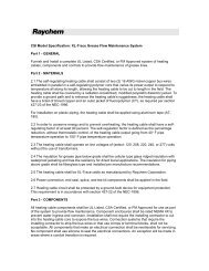
Appendix 3 – Technical Data on TraceTek Operation<br />
TraceTek Operation Diagram<br />
The TraceTek Sensor Interface Module (or board) measures<br />
resistance of each circuit loop independently to ensure the integrity<br />
of the circuit. The resistance of the Yellow-Black loop is used to<br />
compute the Test Length displayed in the detailed channel status<br />
screen (see page 14); it is based on a real-time measurement.<br />
Loop Resistances <strong>and</strong> Test Length<br />
End<br />
termination<br />
Sensing<br />
cable<br />
TTDM-SIM<br />
Red Green Yellow Black<br />
R RG<br />
R YB<br />
The TraceTek Sensor Interface Module (or board) measures current<br />
“leakage” between the two sensing loops. When a leak is<br />
present, the module limits the current to 270 microamps, <strong>and</strong><br />
measures the voltage difference between the yellow <strong>and</strong> black<br />
wires. The resistance along the black sensing wire to the leak is<br />
determined by a simple application of Ohm’s law (R = V/I). The<br />
resistance per unit length of the sensing wire is tightly controlled<br />
in manufacturing, so the location is easily computed.<br />
Leak Current, Resistance, Location<br />
End<br />
termination<br />
Sensing<br />
cable<br />
R S-to-S<br />
R Location<br />
Current<br />
TTDM-SIM<br />
Red Green Yellow Black<br />
DV Leak<br />
DV Location<br />
25