TTDMâNMM and - California Detection Systems
TTDMâNMM and - California Detection Systems
TTDMâNMM and - California Detection Systems

You also want an ePaper? Increase the reach of your titles
YUMPU automatically turns print PDFs into web optimized ePapers that Google loves.
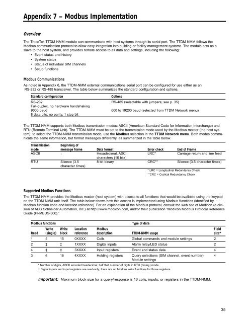
Appendix 7 – Modbus Implementation<br />
Overview<br />
The TraceTek TTDM-NMM module can communicate with host systems through its serial port. The TTDM-NMM follows the<br />
Modbus communication protocol to allow easy integration into building or facility management systems. The module acts as a<br />
slave to the host system, <strong>and</strong> provides remote access to all data <strong>and</strong> settings, including the following:<br />
• Event status <strong>and</strong> history<br />
• System status<br />
• Status of individual SIM channels<br />
• Setup functions<br />
Modbus Communications<br />
As noted in Appendix 6, the TTDM-NMM external communications serial port can be configured for use either as an<br />
RS-232 or RS-485 transceiver. The table below summarizes the st<strong>and</strong>ard configuration <strong>and</strong> options.<br />
St<strong>and</strong>ard configuration<br />
Options<br />
RS-232 RS-485 (selectable with jumpers; see p. 35)<br />
Full-duplex, no hardware h<strong>and</strong>shaking<br />
9600 baud 600 to 19200 baud (selected from TTDM Network menu)<br />
8 data bits, no parity, 1 stop bit<br />
The TTDM-NMM supports both Modbus transmission modes: ASCII (American St<strong>and</strong>ard Code for Information Interchange) <strong>and</strong><br />
RTU (Remote Terminal Unit). The TTDM-NMM must be set to the transmission mode used by the Modbus master (the host system);<br />
to select the TTDM-NMM transmission mode, use the Modbus selection in the TTDM Network menu. Both modes communicate<br />
the same information, but format messages differently, as summarized in the table below.<br />
Transmission Beginning of<br />
mode message frame Data format Error check End of Frame<br />
ASCII : Hexadecimal, ASCII LRC* Carriage return <strong>and</strong> line feed<br />
characters (16 bits)<br />
RTU Silence (3.5 8 bit binary CRC** Silence (3.5 character times)<br />
character times)<br />
* LRC = Longitudinal Redundancy Check<br />
**CRC = Cyclical Redundancy Check<br />
Supported Modbus Functions<br />
The TTDM-NMM provides the Modbus master (host system) with access to all functions that would be available using the keypad<br />
on the TTDM-NMM unit itself. The table below shows how this access is implemented using Modbus functions (identified by<br />
Modbus function code <strong>and</strong> location reference). For an explanation of the Modbus protocol, consult the web site of Modicon (a division<br />
of AEG Schneider Automation, Inc.) at http://www.modicon.com, <strong>and</strong>/or their publication “Modicon Modbus Protocol Reference<br />
Guide (PI-MBUS-300).”<br />
Modbus functions<br />
Type of data<br />
Write Write Location Modbus Field<br />
Read (single) block reference description TTDM-NMM usage size*<br />
1 5 15 0XXXX Coils Global comm<strong>and</strong>s <strong>and</strong> module settings 2<br />
2 ‡ ‡ 1XXXX Digital inputs Alarm relay/LED status 2<br />
4 ‡ ‡ 3XXXX Input registers Event <strong>and</strong> status data 4<br />
3 6 16 4XXXX Holding registers Query selections (SIM channel, event number) 4<br />
Module settings<br />
* Number of digits, ASCII encoded headecimal; half that number of digits in RTU (binary) mode.<br />
‡ Digital inputs <strong>and</strong> input registers are read-only; there are no Modbus write functions for those registers.<br />
Important: Maximum block size for a query/response is 16 coils, inputs, or registers in the TTDM-NMM.<br />
35