TTDMâNMM and - California Detection Systems
TTDMâNMM and - California Detection Systems
TTDMâNMM and - California Detection Systems

Create successful ePaper yourself
Turn your PDF publications into a flip-book with our unique Google optimized e-Paper software.
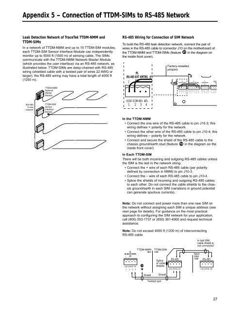
Appendix 5 – Connection of TTDM-SIMs to RS-485 Network<br />
Leak <strong>Detection</strong> Network of TraceTek TTDM-NMM <strong>and</strong><br />
TTDM-SIMs<br />
In a network of TTDM-NMM <strong>and</strong> up to 15 TTDM-SIM modules,<br />
each TTDM-SIM Sensor Interface Module can independently<br />
monitor up to 5000 ft (1500 m) of sensing cable. The SIMs<br />
communicate with the TTDM-NMM Network Master Module<br />
(which provides the user interface) via an RS-485 network, as<br />
illustrated below. TTDM-SIMs are daisy-chained with RS-485<br />
wiring (shielded cable with a twisted pair of wires 22 AWG or<br />
larger); the RS-485 wiring may have a total length of 4000 ft<br />
(1200 m).<br />
RS-485 Wiring for Connection of SIM Network<br />
To build the RS-485 leak detection network, connect the pair of<br />
wires in the RS-485 cable to connector J10 on the motherboard of<br />
the TTDM-NMM <strong>and</strong> TTDM-SIMs (feature 21 in the diagram on<br />
the inside front cover).<br />
PL<br />
RS-485 EXT XMTRS<br />
1<br />
J10<br />
Factory-installed<br />
jumpers<br />
PL<br />
RS-485 EXT XMTRS<br />
1<br />
J10<br />
PL<br />
PL<br />
RS-232/485 EXT COM PORT 4-20MA OUT PORT<br />
1<br />
J13<br />
1<br />
J2<br />
1<br />
SERVICE<br />
5A 25<br />
J6<br />
TTDM-NMM<br />
Network<br />
Master<br />
Module<br />
+51SO<br />
ICOM 485+ 485–<br />
1 2 3 4<br />
RX/A TX/B RTS CTS<br />
+5V GND<br />
5 6 7 8 9 10<br />
IRTN IOUT +V +VRTN<br />
11 12 13 14<br />
NC<br />
NO COM<br />
15 16 17<br />
RS-485<br />
2-wire<br />
network<br />
TTDM-SIM<br />
Sensor<br />
Interface<br />
Module<br />
+51SO ICOM 485+ 485–<br />
1 2 3 4<br />
In the TTDM-NMM<br />
• Connect the one wire of the RS-485 cable to pin J10-3; this<br />
wiring defines + polarity for the network.<br />
• Connect the other wire of the RS-485 cable to pin J10-4; this<br />
wiring defines – polarity for the network.<br />
• Connect <strong>and</strong> secure the shield of the RS-485 cable to the<br />
chassis ground/earth stud (feature 14 in the diagram on the<br />
inside front cover)<br />
In Each TTDM-SIM<br />
There will be both incoming <strong>and</strong> outgoing RS-485 cables unless<br />
the SIM is the last in the network string.<br />
• Connect the + wire of each RS-485 cable (per polarity<br />
defined by connection in NMM) to pin J10-3.<br />
• Connect the – wire of each RS-485 cable to pin J10-4.<br />
• Splice the shields of incoming <strong>and</strong> outgoing RS-485 cables<br />
to each other. Do not connect the cable shields to the chassis<br />
ground/earth in each SIM (variations in ground potential<br />
can generate spurious currents).<br />
Note: Do not connect <strong>and</strong> power more than one new SIM on<br />
the network without assigning each SIM a unique address (see<br />
next page for details). For guidance on the most practical<br />
approach to configuring the SIM network for your application,<br />
call (800) 553-1737 or (650) 361-4900 <strong>and</strong> request technical<br />
assistance.<br />
Note: Do not exceed 4000 ft (1200 m) of interconnecting<br />
RS-485 cable.<br />
PL<br />
RS-485 EXT XMTRS<br />
1<br />
J10<br />
+51SO ICOM 485+ 485–<br />
1 2 3 4<br />
TTDM-NMM<br />
14<br />
TTDM-SIM<br />
Splice<br />
of cable<br />
shields<br />
RS-485<br />
+51SO ICOM 485+ 485–<br />
Next<br />
SIM<br />
In last SIM,<br />
cable shield is<br />
not connected<br />
RS-485<br />
+51SO ICOM 485+ 485–<br />
Shield<br />
Shield<br />
Twisted pair<br />
27