TTDMâNMM and - California Detection Systems
TTDMâNMM and - California Detection Systems
TTDMâNMM and - California Detection Systems

Create successful ePaper yourself
Turn your PDF publications into a flip-book with our unique Google optimized e-Paper software.
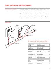
Serial Port<br />
The TTDM-NMM module has a serial port (marked EXT COM<br />
PORT, feature 19 in the diagram on the inside front cover) that<br />
can be configured for use either as an RS-232 or RS-485 transceiver.<br />
The st<strong>and</strong>ard factory configuration is RS-232 full-duplex<br />
with no hardware h<strong>and</strong>shaking, which is suitable for connection<br />
to many devices (such as a remote host PC, laptop, serial printer,<br />
or modem). The st<strong>and</strong>ard setup for the serial port is 9600<br />
baud (adjustable in the TTDM Network menu), 8 data bits, no<br />
parity, <strong>and</strong> 1 stop bit. With the appropriate cable <strong>and</strong> software, a<br />
remote computer can send <strong>and</strong> receive data from a TTDM-NMM<br />
using a st<strong>and</strong>ard terminal emulation program. The TTDM-NMM<br />
follows the Modbus communication protocol (the user can select<br />
either ASCII or RTU mode), so it can be readily integrated into a<br />
building or facility management system.<br />
Wiring Detail for External Communications Serial Port<br />
The serial port for external communications (using either<br />
RS-232 or RS-485) is connector J13 on the TTDM-NMM<br />
motherboard (feature 19 ).<br />
RS-232/485 EXT COM PORT<br />
J13<br />
1<br />
PL<br />
RS-485 EXT XMTRS<br />
1<br />
J10<br />
PL<br />
RS-232/485 EXT COM PORT<br />
1<br />
J13<br />
Connections to External Communications Serial Port<br />
RS-232 Connection Using a 9-Pin D-cable<br />
19<br />
19<br />
RS-232/485 EXT COM PORT<br />
RX TX RTS CTS DTR GND<br />
5 6 7 8 9 10<br />
Shield<br />
RS-232/485 EXT COM PORT<br />
RX TX RTS CTS DTR GND<br />
5 6 7 8 9 10<br />
1 2 3 4 5<br />
6 7 8 9<br />
RS-232 Connection Using a 25-Pin D-cable<br />
14<br />
14<br />
Female<br />
9-pin<br />
D-connector<br />
+51SO<br />
ICOM 485+ 485–<br />
1 2 3 4<br />
RX/A TX/B RTS CTS<br />
+5V GND<br />
5 6 7 8 9 10<br />
RX/A TX/B RTS CTS<br />
+5V GND<br />
5 6 7 8 9 10<br />
RS-232 communications may use either 3 wire (TX, RX, GND)<br />
or 5 wire (with optional RTS/CTS h<strong>and</strong>shaking). RS-485 communications<br />
use 2 wire, half-duplex (A, B). The pinouts for connector<br />
J13 on the TTDM-NMM motherboard are listed below.<br />
RS-485 Connection<br />
Shields<br />
1 2 3 4 5 6 7 8 9 10 11 12 13<br />
14 15 16 17 18 19 20 21 22 23 24 25<br />
Female<br />
25-pin<br />
D-connector<br />
Pin Desc. Use<br />
J13-5 RX/A Receive data for RS-232 or<br />
A(+) terminal for RS-485<br />
J13-6 TX/B Transmit data for RS-232 or<br />
B(-) terminal for RS-485<br />
19<br />
RS-232/485 EXT COM PORT<br />
RX TX RTS CTS DTR GND<br />
5 6 7 8 9 10 14<br />
Shield<br />
RS-485<br />
A<br />
+<br />
B<br />
–<br />
Input<br />
RS-485 to<br />
RS-232<br />
converter<br />
or DCS<br />
The following pins are not used with RS-485:<br />
J13-7 RTS Request to send — for hardware<br />
h<strong>and</strong>shaking, with CTS (optional)<br />
J13-8 CTS Clear to send — for hardware<br />
h<strong>and</strong>shaking, with RTS (optional)<br />
J13-9 +5V/DTR +5 V supply/DTR if needed by<br />
modem (optional)<br />
J13-10 GND Signal ground (earth)<br />
31