- Page 1 and 2:
Infrared Thermal Testing Reading II
- Page 3 and 4:
Infrared Thermography ~-- ... ... .
- Page 5 and 6:
Infrared Thermography Charlie Chong
- Page 7 and 8:
See Through & Fun Thermal Camera Ex
- Page 9 and 10:
How to see through clothing 2 I'
- Page 11 and 12:
Apache IR Thermal Weaponry ■ http
- Page 13 and 14:
Charlie Chong/ Fion Zhang
- Page 15 and 16:
Greek alphabet Letter Name Sound An
- Page 17 and 18:
Greek letter l fl 0 I1 p u w Charli
- Page 19 and 20:
SGuide-IRT Content Part 1 of 2 ■
- Page 21 and 22:
1.1 Introduction to Principles & Th
- Page 23 and 24:
The infrared thermal imaging equipm
- Page 25 and 26:
The three modes of heat transfer ar
- Page 27 and 28:
The three modes of heat transfer ar
- Page 29 and 30:
Temperature and Temperature Scales
- Page 31 and 32:
Boston Tea Party - New governances
- Page 33 and 34:
The Mighty Fahrenheit & ⅝”, Eng
- Page 35 and 36:
Absolute zero is equal to - 273.16
- Page 37 and 38:
The Fourier conduction Law expresse
- Page 39 and 40:
The Fourier conduction Law ( One di
- Page 41 and 42:
Convective Heat Transfer Convective
- Page 43 and 44:
Figure 1.2: Convective heat flow T
- Page 45 and 46:
Newton's cooling law defines the co
- Page 47 and 48:
Radiative Heat Transfer Radiative h
- Page 49 and 50:
Figure 1.4: Infrared radiation leav
- Page 51 and 52:
Thermal infrared radiation impingin
- Page 53 and 54:
Reflections off Specular and Diffus
- Page 55 and 56:
Reflections off Specular and Diffus
- Page 57 and 58:
Radiant Energy Related to Target Su
- Page 59 and 60:
The Stefan-Boltzmann law: W= σƐT
- Page 61 and 62:
Figure 1.6: Typical blackbody distr
- Page 63 and 64:
1.4 Practical Infrared Measurements
- Page 65 and 66:
Characteristics of the Target Surfa
- Page 67 and 68:
Referring back to Figure 1.5, the t
- Page 69 and 70:
Characteristics of the Transmitting
- Page 71 and 72:
Figure 1.10; Transmission of 10m (3
- Page 73 and 74:
Figure 1.11: Transmission, absorpti
- Page 75 and 76:
Figure 1.12: Transmission curves of
- Page 77 and 78:
Chapter 1 Review Questions Q&A 1. b
- Page 79 and 80:
Q4. Heat can only flow in the direc
- Page 81 and 82:
Q10. The follow ing spectral band i
- Page 83 and 84:
Q16. In forced convection, the boun
- Page 85 and 86:
Q22. In the 8 to 14 μm spectral re
- Page 87 and 88:
2.1 Materials Characteristics A kno
- Page 89 and 90:
For an emissivity reference table t
- Page 91 and 92:
Errors because of point source refl
- Page 93 and 94:
View Angle The angle between the in
- Page 95 and 96:
Thermal Conductivity Thermal conduc
- Page 97 and 98:
Thermal Diffusivity As in emissivit
- Page 99 and 100:
Partial 2.1 Table 2.1: d i'ffusivit
- Page 101 and 102:
Partial Table 2.2 Table 2.2: Normal
- Page 103 and 104:
Chapter 2 Review Questions Q&A 1. c
- Page 105 and 106:
4. When measuring the temperature o
- Page 107 and 108:
10. A highly textured surface is sa
- Page 109 and 110:
3.1 Thermal Instrumentation Overvie
- Page 111 and 112:
Thermopile- Thermoelectric Seebeck
- Page 113 and 114:
What is a IR Thermopile? (non-conta
- Page 115 and 116:
IR Thermopile Quad Sensor (non-cont
- Page 117 and 118: Thermocouple A thermocouple is a te
- Page 119 and 120: Bourdon Gas Thermometers 5 f\G.3 0
- Page 121 and 122: Liquid Crystal Thermometer A liquid
- Page 123 and 124: Bimetallic Thermometers Dial Spiral
- Page 125 and 126: In RTD devices; Copper, Nickel and
- Page 127 and 128: Platinum Resistance Thermometer Cha
- Page 129 and 130: RTD Materials Different materials u
- Page 131 and 132: Operations of RTD An RTD takes a me
- Page 133 and 134: Benefits of Thin Film RTD There are
- Page 135 and 136: Thermistor +V r===~ Op A p V to A I
- Page 137 and 138: 3.2 Contacting Thermal Measuring De
- Page 139 and 140: ■ Thermocouple Thermocouples are
- Page 141 and 142: ■ Thermistors Thermistors arc als
- Page 143 and 144: 3.3 Optical Pyrometers Optical pyro
- Page 145 and 146: Pyrometer A pyrometer is a type of
- Page 147 and 148: Brightness Pyrometers -Wien’s Law
- Page 149 and 150: The processing electronics unit amp
- Page 151 and 152: Infrared Detector An infrared detec
- Page 153 and 154: Figure 3.2: Response Curves of Vari
- Page 155 and 156: The mercury cadmium telluride (HgCd
- Page 157 and 158: Infrared Optics - Lenses, Mirrors a
- Page 159 and 160: Field of View (FOV) A field of view
- Page 161 and 162: What is IFOV? A measure of the spat
- Page 163 and 164: Instantaneous Field of View (IFOV)
- Page 165 and 166: 3.5 Scanning and Imaging When probl
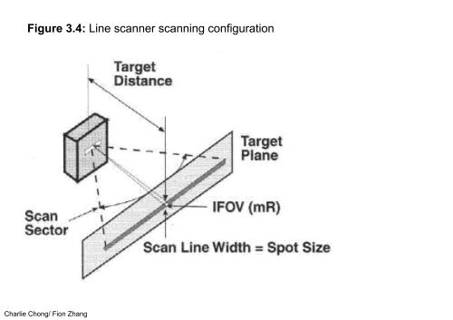
- Page 167: Line Scanning When the measurement
- Page 171 and 172: Figure 3.5: Optomechanlcally scanne
- Page 173 and 174: Pyroelectric Vidicon Thermal Imager
- Page 175 and 176: Figure 3.6: Typical uncooled infrar
- Page 177 and 178: IRFPA Charlie Chong/ Fion Zhang htt
- Page 179 and 180: 3.6 Performance Parameters of Infra
- Page 181 and 182: Performance parameters of qualitati
- Page 183 and 184: Temperature Range Temperature range
- Page 185 and 186: Temperature Sensitivity Temperature
- Page 187 and 188: Speed of Response Speed of response
- Page 189 and 190: Figure 3.7: Instrument speed to res
- Page 191 and 192: Figure 3.8: Instrument field-of-vie
- Page 193 and 194: D ≡ αd D = spot size (approximat
- Page 195 and 196: Output Requirements Output requirem
- Page 197 and 198: Spectral Range Spectral range denot
- Page 199 and 200: Spectrall y selective instrumems us
- Page 201 and 202: Figure 3.9: Spectral response of an
- Page 203 and 204: 3.7 Performance Characteristics of
- Page 205 and 206: The total field of view for a line
- Page 207 and 208: Instantaneous Field of View IFOV In
- Page 209 and 210: Recalling! Temperature sensitivity
- Page 211 and 212: IFOV - MTF The 0.35 MTF refers to:
- Page 213 and 214: Fig. 2a. Slit Response Function. Ca
- Page 215 and 216: Minimum Resolvable Temperature Diff
- Page 217 and 218: EXAM score! D=σ∙d IFOV ratio = d
- Page 219 and 220:
Charlie Chong/ Fion Zhang
- Page 221 and 222:
Answer: D= σ•d, IFOV ration= 1/
- Page 223 and 224:
Break Time - Kenya Coffee Picker Ch
- Page 225 and 226:
Portable Handheld Devices Charlie C
- Page 227 and 228:
Temperature sensitivity and readabi
- Page 229 and 230:
Hand Held Infrared Module Charlie C
- Page 231 and 232:
Note that the laser beam docs not r
- Page 233 and 234:
Emissivity set controls, located in
- Page 235 and 236:
IR Sensor Module Charlie Chong/ Fio
- Page 237 and 238:
IR Sensor Module Charlie Chong/ Fio
- Page 239 and 240:
Two-color Pyrometers or Ratio Pyrom
- Page 241 and 242:
Two-color Pyrometers or Ratio Pyrom
- Page 243 and 244:
Two-color Pyrometers or Ratio Pyrom
- Page 245 and 246:
Phenomena which are non-dynamic in
- Page 247 and 248:
Some ratio thermometers use more th
- Page 249 and 250:
Infrared Radiometric Microscopes Ch
- Page 251 and 252:
Line Scanners Line scanners are div
- Page 253 and 254:
Special Purpose Devices Special pur
- Page 255 and 256:
FLIR- Forward Looking Infrared Char
- Page 257 and 258:
Typically, the total field of view
- Page 259 and 260:
Pyroelectric devices have no direct
- Page 261 and 262:
Figure 3.12: Infrared focal plane a
- Page 263 and 264:
Infrared focal plane array imager C
- Page 265 and 266:
Infrared focal plane array imager C
- Page 267 and 268:
On-board capabilities include isoth
- Page 269 and 270:
ccc Electron Microscope Image of mi
- Page 271 and 272:
Platinum Silicide IrFPA 19 t«lU 98
- Page 273 and 274:
Quantitative IR Image Charlie Chong
- Page 275 and 276:
Quantitative Thermal Measurements S
- Page 277 and 278:
In addition to the spot measurement
- Page 279 and 280:
Stored images can be retrieved, dis
- Page 281 and 282:
Calibration Accessories Infrared ra
- Page 283 and 284:
Online printers and plotters are re
- Page 285 and 286:
Q1. The thermal resolution of an in
- Page 287 and 288:
Q7. The 3 to 5 μm spectral region
- Page 289 and 290:
Q13. A line scanner can be used to
- Page 291 and 292:
Q19. For which of the following app
- Page 293 and 294:
Q25. Two-color (ratio) pyrometers m
- Page 295 and 296:
Chapter 4 Operating Equipment and U
- Page 297 and 298:
■ Emissivity Differences ∆τ Em
- Page 299 and 300:
Causes of Real Temperature Changes
- Page 301 and 302:
Mass Transport Differences (Fluid F
- Page 303 and 304:
Figure 4.1: An indication of water
- Page 305 and 306:
Thermal Capacitance Differences ∆
- Page 307 and 308:
■ Induced Heating Differences (by
- Page 309 and 310:
Induced Heating Differences Charlie
- Page 311 and 312:
■ Energy Conversion Differences E
- Page 313 and 314:
Figure 4.3: Catalytic reformer vess
- Page 315 and 316:
Infrared Thermogram Energy Conversi
- Page 317 and 318:
Infrared Thermogram Energy Conversi
- Page 319 and 320:
■ Combination of Heat Transfer Me
- Page 321 and 322:
Infrared Thermogram of a running mo
- Page 323 and 324:
■ Spectral Considerations in Prod
- Page 325 and 326:
Infrared Thermogram Charlie Chong/
- Page 327 and 328:
Infrared Thermogram ..... " I Charl
- Page 329 and 330:
Figure 4.5: Spectral selectivity fo
- Page 331 and 332:
Figure 4.7: temperature thermogram
- Page 333 and 334:
Figure 4.8 shows the transmission s
- Page 335 and 336:
Figure 4.9: Measuring temperature o
- Page 337 and 338:
IR Filter Charlie Chong/ Fion Zhang
- Page 339 and 340:
Figure 4.10: Line scanner for conti
- Page 341 and 342:
Preparation of Equipment for Operat
- Page 343 and 344:
If the instrument is out of cal ibr
- Page 345 and 346:
The batteries mentioned on the miss
- Page 347 and 348:
Comments: ■ ■ ■ Thermal resol
- Page 349 and 350:
Figure 4.11 : Test configuration fo
- Page 351 and 352:
3. Reduce the ΔT until the image i
- Page 353 and 354:
■ Imaging Spatial Resolution Imag
- Page 355 and 356:
A sample setup is illustrated in Fi
- Page 357 and 358:
5. If the modulation transfer funct
- Page 359 and 360:
Figure 4.13: Test configuration for
- Page 361 and 362:
4. Open slit until V meas = V max .
- Page 363 and 364:
■ Learning the Startup Procedure
- Page 365 and 366:
■ Setting the Correct Effective E
- Page 367 and 368:
Figure 4.14: Test configuration for
- Page 369 and 370:
■ Measuring and Reporting Tempera
- Page 371 and 372:
■ Recognizing and Avoiding Reflec
- Page 373 and 374:
■ Measuring the Appropriate Backg
- Page 375 and 376:
■ Temperature Differences Between
- Page 377 and 378:
■ Liquid and Compressed Gases Som
- Page 379 and 380:
Dewar Flask for LN Loosely fitting
- Page 381 and 382:
■ Electrical Safety Failure to re
- Page 383 and 384:
Table 4.1: Electric shock current t
- Page 385 and 386:
4.4 Record Keeping Keeping thorough
- Page 387 and 388:
Easily accessible and easily unders
- Page 389 and 390:
Q1. Apparent but not real temperatu
- Page 391 and 392:
Q5. The higher the temperature of a
- Page 393 and 394:
Q9. Differential thermography can b
- Page 395 and 396:
5.1 Overview of Applications Becaus
- Page 397 and 398:
Electrical Applications Electrical
- Page 399 and 400:
High electrical resistance is the m
- Page 401 and 402:
Excessive heating due to a defectiv
- Page 403 and 404:
Inductive currents flowing with in
- Page 405 and 406:
Moisture in Airframes The detection
- Page 407 and 408:
Process Control and Product Monitor
- Page 409 and 410:
The differences produced by this co
- Page 411 and 412:
Night Vision, Seareh, Surveillance,
- Page 413 and 414:
Thermogram of helicopter taken at n
- Page 415 and 416:
Aircraft Under IR Trap Charlie Chon
- Page 417 and 418:
Instruments used for these applicat
- Page 419 and 420:
8 to 12 μm spectral region over wh
- Page 421 and 422:
Animal Studies Body heat allows inf
- Page 423 and 424:
Injured equine foreleg (left) appea
- Page 425 and 426:
Work energy is expended by friction
- Page 427 and 428:
5.4 Fluid Flow Investigations For s
- Page 429 and 430:
Figure 1.7: Thermographs of valve (
- Page 431 and 432:
■ Building Insulation and Other F
- Page 433 and 434:
Figures 5.8 and 5.9 illustrate thes
- Page 435 and 436:
Figure 5.9: Example of air exfiltra
- Page 437 and 438:
Example of air exfiltration Charlie
- Page 439 and 440:
■ Refractory Systems Industrial s
- Page 441 and 442:
Refractory Thermogram Charlie Chong
- Page 443 and 444:
■ Subsurface Discontinuity Detect
- Page 445 and 446:
Figure 5.11: An example of passive
- Page 447 and 448:
The equipment necessary to perform
- Page 449 and 450:
Figure 5.12: Example of active (hea
- Page 451 and 452:
Typical failure modes of the materi
- Page 453 and 454:
Figure 5.13: Test of aircraft deici
- Page 455 and 456:
DC - 9 Charlie Chong/ Fion Zhang
- Page 457 and 458:
Figure 5.14: Conceptual sketch of t
- Page 459 and 460:
In this case. however, the heat pul
- Page 461 and 462:
Figure 5.15: Erosion/corrosion dama
- Page 463 and 464:
737 aircraft Charlie Chong/ Fion Zh
- Page 465 and 466:
When there has been adequate solar
- Page 467 and 468:
Liquid Level Detection Thermal capa
- Page 469 and 470:
Unstimulated and Stimulated Approac
- Page 471 and 472:
Subsurface Discontinuity Detection
- Page 473 and 474:
1. A major area of infrared nondest
- Page 475 and 476:
5. The diagnostics involved in dete
- Page 477 and 478:
9. Thermography has been successful
- Page 479 and 480:
Appendix A Glossary The following a
- Page 481 and 482:
Ambient temperature - Temperature o
- Page 483 and 484:
Figure A-1 Apparent ambient tempera
- Page 485 and 486:
13.Blackbody, blackbody radiator -
- Page 487 and 488:
Alas! Heat Capacity Volumetric = C
- Page 489 and 490:
27.Detector, infrared - A transduce
- Page 491 and 492:
Thermal Effusivity In Thermodynamic
- Page 493 and 494:
Alas! Exitance = Rodiosity for my A
- Page 495 and 496:
45.Frame repetition rate - The time
- Page 497 and 498:
Thermal Inertia Thermal inertia is
- Page 499 and 500:
Instantaneous field of View (lFOV)
- Page 501 and 502:
Laser pyrometer - Laser pyrometer -
- Page 503 and 504:
Figure 3.2: Response Curves of Vari
- Page 505 and 506:
Compare: Minimum resolvable tempera
- Page 507 and 508:
86.Radiation rererenee source - A b
- Page 509 and 510:
101. Sector - For a line scanner, a
- Page 511 and 512:
113. Subtense, angular - The angula
- Page 513 and 514:
121. Thermal wave imaging - A term
- Page 515 and 516:
125. Thermogram - A thermal map or
- Page 517 and 518:
Appendix B Cost Benefit Determinati
- Page 519 and 520:
Although the calculations are quite
- Page 521 and 522:
96 ASNT Level Ill Study Guide: Infr
- Page 523 and 524:
Appendix C, Commonly Used Infrared
- Page 525 and 526:
Appendix C, Commonly Used Infrared
- Page 527 and 528:
Peach - 我 爱 桃 子 Charlie Cho
- Page 529 and 530:
Good Luck Charlie Chong/ Fion Zhang