TeSys protection components - Trinet
TeSys protection components - Trinet
TeSys protection components - Trinet

You also want an ePaper? Increase the reach of your titles
YUMPU automatically turns print PDFs into web optimized ePapers that Google loves.
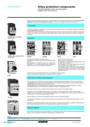
Selection<br />
<strong>TeSys</strong> contactors<br />
For utilisation category AC-1<br />
Maximum operational current (open-mounted device)<br />
Contactor<br />
LC1- LC1- LC1- LC1- LC1- LC1- LC1- LC1- LC1- LC1- LC1-<br />
size LP1- LP1- LP1-<br />
K09 K12 D09 D12 D18 D25 D32 D38 D40<br />
DT20 DT25 DT32 DT40 DT60<br />
Maximum operating rate<br />
in operating cycles/hour 600 600 600 600 600 600 600 600 600 600 600<br />
Connections/ cable c.s.a. mm 2 4 4 4 4 4 6 6 10 16 10 16<br />
cabling conforming<br />
to IEC 947-1 bar size mm – – – – – – – – – – –<br />
Operational current<br />
in AC-1 in A, ≤ 40 °C A 20 20 25 20 25 32 40 50 60 50 60<br />
according to the<br />
ambient temperat- ≤ 60 °C A 20 20 25 20 25 32 40 50 60 50 60<br />
ure, conforming to<br />
IEC 947-1 ≤ 70 °C A (at Uc)(1) (1) 17 (1) 17 22 28 35 45 35 42<br />
Maximum 220/230 V kW 8 8 9 8 9 11 14 18 21 18 21<br />
operational<br />
power 240 V kW 8 8 9 8 9 12 15 19 23 19 23<br />
≤ 60 °C<br />
380/400 V kW 14 14 15 14 15 20 25 31 37 31 37<br />
415 V kW 14 14 17 14 17 21 27 34 41 34 41<br />
440 V kW 15 15 18 15 18 23 29 36 43 36 43<br />
500 V kW 17 17 20 17 20 23 33 41 49 41 49<br />
660/690 V kW 22 22 27 22 27 34 43 54 65 54 65<br />
1000 V kW – – – – – – – – – – 70<br />
(1) Please consult your Regional Sales Office.<br />
Increase in operational current by parallelling of poles<br />
Apply the following multiplying factors to the current values given above. The factors take into account the often unbalanced<br />
current distribution between phases: - 2 poles in parallel: K = 1.6<br />
- 3 poles in parallel: K = 2.25<br />
- 4 poles in parallel: K = 2.8<br />
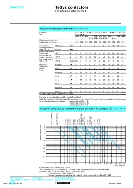
Selection according to required electrical durability, in category AC-1 (Ue ≤ 440 V)<br />
Millions of operating cycles<br />
10<br />
8<br />
6<br />
4<br />
2<br />
1,5<br />
LC1, LP1, LP4-K09<br />
LC1, LP1, LP4-K12<br />
LC1-D09<br />
LC1-DT20<br />
LC1-D12<br />
LC1-DT25<br />
LC1-D18<br />
LC1-DT32<br />
LC1-D25<br />
LC1-DT40<br />
LC1-D32, LC1-D38<br />
LC1-DT60<br />
LC1, LP1-D40<br />
LC1-D50<br />
LC1, LP1-D65<br />
LC1, LP1-D80<br />
LC1-D95<br />
LC1-D115<br />
LC1-D150<br />
1<br />
0,8<br />
0,6<br />
0,4<br />
0,2<br />
Characteristics:<br />
pages 24505/2 to 24505/7<br />
24561_Ver2.20-EN.fm/2<br />
0,1<br />
1 2 3 4 6 8 10<br />
20 25 32 40 50 60 80 100 125 200 250 400<br />
Current broken in A<br />
Control of resistive circuits (cos ϕ ≥ 0.95).<br />
The current broken (Ic) in category AC-1 is equal to the current (Ie) normally drawn by the load.<br />
Example: Ue = 220 V - Ie = 50 A - θ≤40 °C - Ic = Ie = 50 A.<br />
2 million operating cycles required.<br />
The above selection curves show the contactor rating needed: either LC1 or LP1-D50.<br />
References:<br />
pages 24501/2 to 24502/3<br />
Dimensions, schemes:<br />
pages 24531/2 to 24532/3<br />
Schneider Electric