TeSys protection components - Trinet
TeSys protection components - Trinet
TeSys protection components - Trinet

Create successful ePaper yourself
Turn your PDF publications into a flip-book with our unique Google optimized e-Paper software.
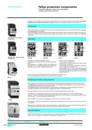
Selection<br />
<strong>TeSys</strong> contactors<br />
For lighting circuits<br />
General<br />
The operating conditions of lighting circuits have the following characteristics:<br />
- continuous duty: the switching device can remain closed for several days or even months,<br />
- a dispersion factor of 1: all luminaires in the same group are switched on or off simultaneously,<br />
- a relatively high temperature around the device due to the enclosure, the presence of fuses, or an unventilated control<br />
panel location.<br />
This is why the operational current for lighting is lower than the value given for AC-1 duty.<br />
Protection The continuous duty current drawn by a lighting circuit is constant. In effect :<br />
- it is unlikely that the number of lighting fittings of an existing circuit will be modified,<br />
- this type of circuit cannot create an overload of long duration.<br />
This is why only short-circuit <strong>protection</strong> is necessary for these circuits.<br />
It can be provided by:<br />
- gG type fuses, or<br />
- modular circuit-breakers.<br />
Nevertheless it is always possible and sometimes more economical (small cable size) to protect the circuit by a thermal<br />
overload relay and associated aM type fuses.<br />
Distribution system<br />
p Single-phase circuit, 220/240 V<br />
The tables on pages 24567/3 to 24567/5 are based on a single-phase 220/240 V circuit and can therefore be applied<br />
directly in this case.<br />
p 3-phase circuit, 380/415 V with neutral<br />
The total number of lamps (N) to be switched simultaneously is divided into three equal groups, each<br />
connected between one phase and neutral. The contactor can then be selected from the 220/240 V singlephase<br />
table for a number of lamps equal to N<br />
---<br />
3<br />
p 3-phase circuit, 220/240 V<br />
The total number of lamps (N) to be switched simultaneously is divided into three equal groups, each connected<br />
between 2phases (L1-L2), (L2-L3), (L3-L1). The contactor can then be selected from the 220/240 V single-phase table<br />
for a number of lamps equal to N<br />
------<br />
3<br />
Contactor selection tables<br />
For the different types of lamps, the tables on pages 24567/3 to 24567/5 give the maximum number of lamps of unit power<br />
P (in Watts), which can be switched simultaneously for each size of contactor.<br />
They are based on:<br />
- a 220/240 V single-phase circuit,<br />
- an ambient temperature of 55 °C (1), taking into account the operating conditions (see General paragraph).<br />
- an electrical life of more than 10 years (200 days' operation per year).<br />
They take into account:<br />
- the total current drawn (including ballast),<br />
- transient phenomena which occur at switch-on,<br />
- the starting currents and their duration,<br />
- the circulation of any harmonics which may be present.<br />
Lamps with compensating capacitor C (µF) connected in parallel<br />
Parallel connected compensating capacitors C cause a current peak at the moment of switch-on. To ensure that the value<br />
of this current peak remains compatible with the making characteristics of the contactors, the unit value of the<br />
capacitance must not exceed the following:<br />
Switching LC1- LP1- LC1- LC1- LC1- LC1- LC1- LC1- LC1- LC1- LC1- LC1- LC1-<br />
contactor size K09 K09 D09 D12 D18 D25 D32 D38 D40 D50 D65 D80 D95<br />
Maximum unit value C (µF)<br />
of compensating capacitor 7 3 18 18 25 60 96 96 120 120 240 240 240<br />
connected in parallel<br />
Switching<br />
LC1- LC1- LC1- LC1- LC1- LC1- LC1- LC1- LC1- LC1-<br />
contactor size<br />
D115 D150 F185 F225 F265 F330 F400 F500 F630 F800<br />
Maximum unit value C (µF)<br />
of compensating capacitor 300 360 800 1200 1700 2500 4000 6000 9000 10 800<br />
connected in parallel<br />
This value is independent of the number of lamps switched by the contactor.<br />
(1) For an ambient temperature of 40 °C, multiply the number by 1.2.<br />
Characteristics :<br />
pages 24505/2 to 24505/7<br />
References :<br />
pages 24501/2 to 24502/3<br />
Dimensions :<br />
pages 24531/2 to 24531/5<br />
Schemes :<br />
pages 24532/2 and 24532/3<br />
4567 Ver2.00-EN.fm/2 Schneider Electric