TeSys protection components - Trinet
TeSys protection components - Trinet
TeSys protection components - Trinet

Create successful ePaper yourself
Turn your PDF publications into a flip-book with our unique Google optimized e-Paper software.
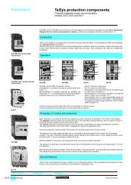
Schemes (switch functions)<br />
Installation system<br />
Tego Power for motor power-starter <strong>components</strong><br />
Communication modules<br />
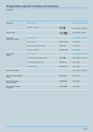
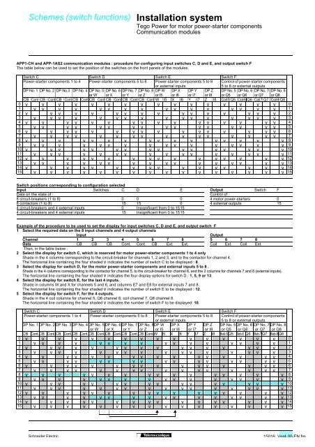
APP1-CH and APP-1AS2 communication modules : procedure for configuring input switches C, D and E, and output switch F<br />
The table below can be used to set the position of the switches on the front panels of the modules.<br />
Switch C Switch D Switch E Switch F<br />
Power-starter <strong>components</strong> 1 to 4 Power-starter <strong>components</strong> 5 to 8 Power-starter <strong>components</strong> 5 to 8 Control of power-starter <strong>components</strong><br />
or external inputs<br />
5 to 8 or external outputs<br />
DP No. 1 DP No. 2 DP No.3 DP No. 4 DP No. 5 DP No. 6 DP No. 7 DP No. 8 DP W DP X DP Y DP Z DP No. 5 DP No. 6 DP No. 7 DP No. 8<br />
or W or X or Y or Z or I5 or I6 or I7 or I8 or Q5 or Q6 or Q7 or Q8<br />
CB Cont CB Cont CB Cont CB Cont CB Cont CB Cont CB Cont CB Cont W I5 X I6 Y I7 Z I8 Coil 5 Q5 Coil 6 Q6 Coil 7 Q7 Coil 8 Q8<br />
0 v v v v v v v v v v v v v v v v 0<br />
1 v v v v v v v v v v v v v v v v 1<br />
2 v v v v v v v v v v v v v v v v 2<br />
3 v v v v v v v v v v v v v v v v 3<br />
4 v v v v v v v v v v v v v v v v 4<br />
5 v v v v v v v v v v v v v v v v 5<br />
6 v v v v v v v v v v v v v v v v 6<br />
7 v v v v v v v v v v v v v v v v 7<br />
8 v v v v v v v v v v v v v v v v 8<br />
9 v v v v v v v v v v v v v v v v 9<br />
10 v v v v v v v v v v v v v v v v 10<br />
11 v v v v v v v v v v v v v v v v 11<br />
12 v v v v v v v v v v v v v v v v 12<br />
13 v v v v v v v v v v v v v v v v 13<br />
14 v v v v v v v v v v v v v v v v 14<br />
15 v v v v v v v v v v v v v v v v 15<br />
Switch positions corresponding to configuration selected<br />
Input Switches C D E Output Switch F<br />
Data on the state of : Control of :<br />
8 circuit-breakers (1 to 8) 0 0 0 4 motor power-starters 0<br />
8 contactors (1 to 8) 15 15 0 4 external outputs 15<br />
4 circuit-breakers and 4 external inputs 0 Insignificant from 0 to 1515<br />
4 circuit-breakers and 4 external inputs 15 Insignificant from 0 to 1515<br />
Example of the procedure to be used to set the display for input switches C, D and E, and output switch F<br />
1 Select the required data on the 8 input channels and 4 output channels<br />
Input<br />
Output<br />
Channel 1 2 3 4 5 6 7 8 5 6 7 8<br />
Data CB CB CB Cont. Cont. CB Ext. Ext. Coil Ext. Coil Ext.<br />
Then, in the table below :<br />
2 Select the display for switch C, which is reserved for motor power-starter <strong>components</strong> 1 to 4 only<br />
Shade in the 4 columns corresponding to the circuit-breaker for channels 1, 2 and 3, and to the contactor for channel 4.<br />
The horizontal line containing the four shaded v indicates the number of switch C to be displayed : 8.<br />
3 Select the display for switch D, for the motor power-starter <strong>components</strong> and external inputs 5 to 8 .<br />
Shade in the 4 columns corresponding to the contactor for channel 5, to the circuit-breaker for channel 6, and the 2 columns for channels 7 and 8 (external inputs).<br />
The horizontal line containing the four shaded v indicates the four display options for switch D : 1, 5, 9 or 13.<br />
4 Select the display for switch E, for the last 4 inputs.<br />
Shade in columns W and X for channels 5 and 6, and columns E7 and E8 for external inputs 7 and 8.<br />
The horizontal line containing the four shaded v indicates the number of switch E to be displayed : 12.<br />
5 Select the display for switch F, for the 4 outputs.<br />
Shade in the 4 coil columns for channel 5, Q6 channel 6, coil channel 7, Q8 channel 8.<br />
The horizontal line containing the four shaded v indicates the number of switch F to be displayed: 10.<br />
Switch C Switch D Switch E Switch F<br />
Power-starter <strong>components</strong> 1 to 4 Power-starter <strong>components</strong> 5 to 8 Power-starter <strong>components</strong> 5 to 8 Control of power-starter <strong>components</strong><br />
or external inputs<br />
5 to 8 or external outputs<br />
DP No. 1 DP No. 2 DP No. 3 DP No. 4 DP No. 5 DP No. 6 DP No. 7 DP No. 8DP W DP X DP Y DP Z DP No. 5 DP No. 6 DP No. 7 DP No. 8<br />
or W or X or Y or Z or I5 or I6 or I7 or I8 or Q5 or Q6 or Q7 or Q8<br />
CB Cont.CB Cont.CB Cont.CB Cont.CB Cont.CB Cont.CB Cont.CB Cont.W I5 X I6 Y I7 Z I8 Bob.5Q5 Bob.6 Q6 Bob.7Q7 Bob.8Q8<br />
0 v v v v v v v v v v v v v v v v 0<br />
1 v v v v v v v v v v v v v v v v 1<br />
2 v v v v v v v v v v v v v v v v 2<br />
3 v v v v v v v v v v v v v v v v 3<br />
4 v v v v v v v v v v v v v v v v 4<br />
5 v v v v v v v v v v v v v v v v 5<br />
6 v v v v v v v v v v v v v v v v 6<br />
7 v v v v v v v v v v v v v v v v 7<br />
8 v v v v v v v v v v v v v v v v 8<br />
9 v v v v v v v v v v v v v v v v 9<br />
10 v v v v v v v v v v v v v v v v 10<br />
11 v v v v v v v v v v v v v v v v 11<br />
12 v v v v v v v v v v v v v v v v 12<br />
13 v v v v v v v v v v v v v v v v 13<br />
14 v v v v v v v v v v v v v v v v 14<br />
15 v v v v v v v v v v v v v v v v 15<br />
Schneider Electric<br />
15016 Ver4.00-EN.fm/