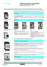
TeSys protection components - Trinet
TeSys protection components - Trinet
TeSys protection components - Trinet

Create successful ePaper yourself
Turn your PDF publications into a flip-book with our unique Google optimized e-Paper software.
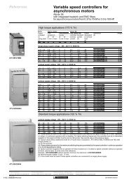
Selection<br />
<strong>TeSys</strong> contactors<br />
For switching 3-phase capacitor banks<br />
used for power factor correction<br />
Standard contactors<br />
Capacitors, together with the circuits to which they are connected, form oscillatory circuits which can, at the moment of<br />
switch-on, give rise to high transient currents (> 180 In) at high frequencies (1 to 15 kHz).<br />
As a general rule, the peak current on energisation is lower when:<br />
- the mains inductances are high,<br />
- the line transformer ratings are low,<br />
- the transformer short-circuit voltage is high,<br />
- the ratio between the sum of the ratings of the capacitors already switched into the circuit and that of the capacitors<br />
to be switched in is small (for multiple step capacitor banks).<br />
In accordance with standards IEC 70, NF C 54-100, VDE 0560, the switching contactor must be able to withstand a<br />
continuous current of 1.43 times the rated current of the capacitor bank step being switched.<br />
The rated operational powers given in the tables opposite take this overload into account.<br />
Short-circuit <strong>protection</strong> is normally provided by gI type HPC fuses rated at 1.7 to 2 In.<br />
Contactor applications<br />
Operating conditions<br />
Capacitors are directly switched. The values of peak current at switch-on must not exceed the values indicated<br />
opposite.<br />
An inductor may be inserted in each of the three phases supplying the capacitors to reduce the peak current, if necessary.<br />
Inductance values are determined according to the selected operating temperature.<br />
Power factor correction by a single-step capacitor bank<br />
The use of a choke inductor is unnecessary: the inductance of the mains supply is adequate to limit the peak to a value<br />
compatible with the contactor characteristics.<br />
Power factor correction by a multiple-step capacitor bank<br />
Select a special contactor as defined on page 24569/2.<br />
If a standard contactor is used, it is essential to insert a choke inductor in each of the three phases of each step.<br />
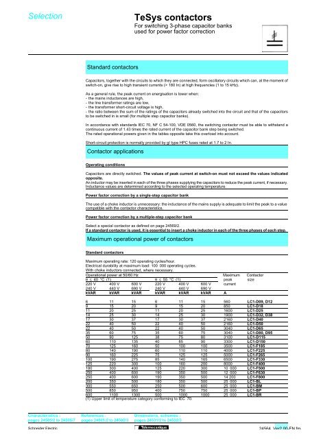
Maximum operational power of contactors<br />
Standard contactors<br />
Maximum operating rate: 120 operating cycles/hour.<br />
Electrical durability at maximum load: 100 000 operating cycles.<br />
With choke inductors connected, where necessary.<br />
Operational power at 50/60 Hz Maximum Contactor<br />
θ ≤ 40 °C (1) θ ≤ 55 °C (1) peak size<br />
220 V 400 V 600 V 220 V 400 V 600 V current<br />
240 V 440 V 690 V 240 V 440 V 690 V<br />
kVAR kVAR kVAR kVAR kVAR kVAR A<br />
6 11 15 6 11 15 560 LC1-D09, D12<br />
9 15 20 9 15 20 850 LC1-D18<br />
11 20 25 11 20 25 1600 LC1-D25<br />
14 25 30 14 25 30 1900 LC1-D32, D38<br />
17 30 37 17 30 37 2160 LC1-D40<br />
22 40 50 22 40 50 2160 LC1-D50<br />
22 40 50 22 40 50 3040 LC1-D65<br />
35 60 75 35 60 75 3040 LC1-D80, D95<br />
50 90 125 38 75 80 3100 LC1-D115<br />
60 110 135 40 85 90 3300 LC1-D150<br />
70 125 160 50 100 100 3500 LC1-F185<br />
80 140 190 60 110 110 4000 LC1-F225<br />
90 160 225 75 125 125 5000 LC1-F265<br />
100 190 275 85 140 165 6500 LC1-F330<br />
125 220 300 100 160 200 8000 LC1-F400<br />
180 300 400 125 220 300 10 000 LC1-F500<br />
250 400 600 190 350 500 12 000 LC1-F630<br />
250 400 600 190 350 500 14 200 LC1-F800<br />
200 350 500 180 350 500 25 000 LC1-BL<br />
300 550 650 250 500 600 25 000 LC1-BM<br />
500 850 950 400 750 750 25 000 LC1-BP<br />
600 1100 1300 500 1000 1000 25 000 LC1-BR<br />
(1) Upper limit of temperature category conforming to IEC 70.<br />
Characteristics :<br />
pages 24505/2 to 24505/7<br />
References :<br />
pages 24501/2 to 24502/3<br />
Dimensions, schemes :<br />
pages 24531/2 to 24532/3<br />
Schneider Electric<br />
24564 Ver2.00-EN.fm/