TeSys protection components - Trinet
TeSys protection components - Trinet
TeSys protection components - Trinet

You also want an ePaper? Increase the reach of your titles
YUMPU automatically turns print PDFs into web optimized ePapers that Google loves.
References<br />
<strong>TeSys</strong> control relays<br />
7<br />
Model d control relays<br />
Add-on blocks<br />
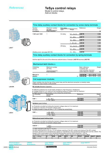
Time delay auxiliary contact blocks for connection by screw clamp terminals<br />
Number Maximum number Time delay Reference Weight<br />
and type per relay Type Range<br />
of contacts Front mounting kg<br />
1 N/C and 1 N/O 1 On-delay 0.1…3 s (1) LAD-T0 0.060<br />
0.1…30 s LAD-T2 0.060<br />
10…180 s LAD-T4 0.060<br />
1…30 s (2) LAD-S2 0.060<br />
LAD-T<br />
Off-delay 0.1…3 s (1) LAD-R0 0.060<br />
0.1…30 s LAD-R2 0.060<br />
(Sealing cover: see page 24511/9) 10…180 s LAD-R4 0.060<br />
Time delay auxiliary contact blocks for connection by spring terminals<br />
Add the digit 3 to the end of the references selected above. Example: LAD-T0 becomes LAD-T03.<br />
Mechanical latch blocks (3)<br />
Unlatching Maximum number Basic reference. Weight<br />
control per relay Complete with<br />
code indicating Standard<br />
Front mounting control voltage (4) voltages kg<br />
Manual or 1 LA6-DK10/ BEFMQ 0.070<br />
electric or LAD-6K10/ BEFMQ 0.070<br />
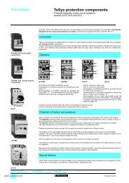
Coil suppressor modules<br />
These modules clip onto the top of the control relay and the electrical connection is instantly made.<br />
Fitting of an input module is still possible.<br />
LA6-DK<br />
RC circuits (Resistor-Capacitor)<br />
/ Effective <strong>protection</strong> for circuits highly sensitive to “high frequency” interference.<br />
/ Voltage limited to 3 Uc maximum and oscillating frequency limited to 400 Hz maximum.<br />
/ Slight increase in drop-out time (1.2 to 2 times the normal time).<br />
For mounting Operational Reference Weight<br />
on voltage kg<br />
CAD " " 24…48 V LAD-4RCE 0.012<br />
" 110…240 V LAD-4RCU 0.012<br />
Varistors (peak limiting)<br />
/ Protection provided by limiting the transient voltage value to 2 Uc maximum.<br />
/ Maximum reduction of transient voltage peaks.<br />
/ Slight increase in drop-out time (1.1 to 1.5 times the normal time).<br />
LAD-4<br />
CAD " " 24…48 V LAD-4VE 0.012<br />
" 50…127 V LAD-4VG 0.012<br />
" 110…250 V LAD-4VU 0.012<br />
Bidirectional peak limiting diode<br />
/ Protection provided by limiting the transient voltage value to 2 Uc maximum.<br />
/ Maximum reduction of transient voltage peaks.<br />
CAD-N " " 24 V LAD-4TB 0.012<br />
" 72 V LAD-4TS 0.012<br />
(1) With extended scale from 0.1 to 0.6 s.<br />
(2) With switching time of 40 ms ± 15 ms between opening of the N/C contact and closing of the N/O contact.<br />
(3) Power should not be simultaneously applied or maintained to the mechanical latching block and the CAD-N. The<br />
duration of the control signal to the mechanical latching block and the CAD-N should be ≥ 100 ms.<br />
(4) Standard control circuit voltages (for other voltages, please consult your Regional Sales Office).<br />
Volts " and $ 24 32/36 42/48 60/72 100 110/127 220/240 256/277 380/415<br />
Code B C E EN K F M U Q<br />
Characteristics:<br />
pages 24526/2 and<br />
24526/3<br />
Illustrations:<br />
page 24525/2<br />
Dimensions:<br />
page 24537/2<br />
Schemes:<br />
page 24537/3<br />
24525_Ver5.31-EN.fm/4<br />
Schneider Electric