TeSys protection components - Trinet
TeSys protection components - Trinet
TeSys protection components - Trinet

You also want an ePaper? Increase the reach of your titles
YUMPU automatically turns print PDFs into web optimized ePapers that Google loves.
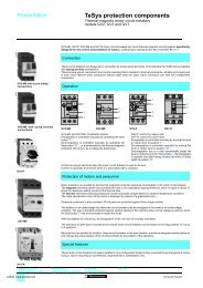
General<br />
<strong>TeSys</strong> contactors<br />
Long distance remote control<br />
Voltage drop caused by the inrush current<br />
When the operating coil of a contactor is energised, the inrush current produces a voltage drop in the control supply<br />
cable caused by the resistance of the conductors, which can adversely affect closing of the contactor.<br />
An excessive voltage drop in the control supply cables (both a.c. and d.c.) can lead to non closure of the contactor poles<br />
or even destruction of the coil due to overheating.<br />
This phenomenon is aggravated by:<br />
- a long line,<br />
- a low control circuit voltage,<br />
- a cable with a small c.s.a.,<br />
- a high inrush power drawn by the coil.<br />
The maximum length of cable, depending on the control voltage, the inrush power and the conductor c.s.a. is indicated<br />
in the graphs below.<br />
Remedial action<br />
To reduce the voltage drop at switch-on:<br />
- increase the conductor c.s.a.<br />
- use a higher control circuit voltage<br />
- use an intermediate control relay.<br />
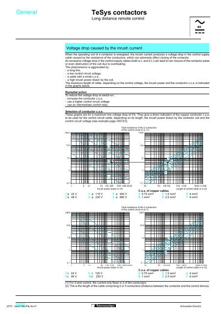
Selection of conductor c.s.a.<br />
These graphs are for a maximum line voltage drop of 5%. They give a direct indication of the copper conductor c.s.a.<br />
to be used for the control circuit cable, depending on its length, the inrush power drawn by the contactor coil and the<br />
control circuit voltage (see example page 24572/3).<br />
Total resistance of the 2 conductors<br />
of the control circuit in Ω (1)<br />
Inrush power drawn in VA<br />
C.s.a. of copper cables<br />
Length of control cable in m (2)<br />
1a 24 V 3 a 115 V 5 a 400 V A 0.75 mm2 C 1.5 mm2 E 4 mm2<br />
2a 48 V 4 a 230 V 6 a 690 V B 1 mm 2 D 2.5 mm 2 F 6 mm 2<br />
Total resistance of the 2 conductors<br />
of the control circuit in Ω (1)<br />
Inrush power drawn in VA Length of control cable in m (2)<br />
C.s.a. of copper cables<br />
7c 24 V 9 c 125 V A 0.75 mm 2 C 1.5 mm 2 E 4 mm 2<br />
8c 48 V 10 c 250 V B 1 mm 2 D 2.5 mm 2 F 6 mm 2<br />
(1) For 3-wire control, the current only flows in 2 of the conductors.<br />
(2) This is the length of the cable comprising 2 or 3 conductors (Distance between the contactor and the control device).<br />
4572 Ver2.00-EN.fm/2 Schneider Electric