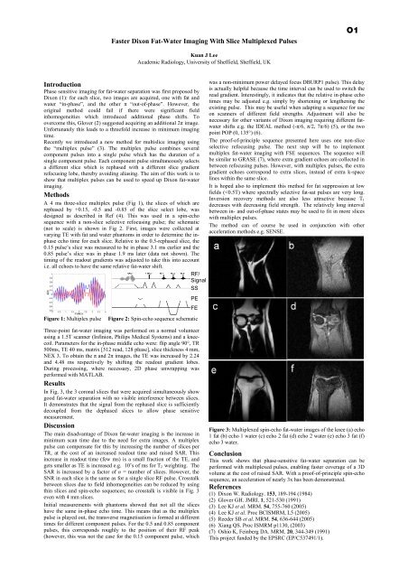
Faster Dixon Fat-Water Imaging With Slice Multiplexed PulsesO1Kuan J LeeAcademic Radiology, <strong>University</strong> <strong>of</strong> Sheffield, Sheffield, UKIntroductionPhase sensitive imaging for fat-water separation was first proposed byDixon (1): for each slice, two images are acquired, one with fat andwater “in-phase”, and <strong>the</strong> o<strong>the</strong>r π “out-<strong>of</strong>-phase”. However, <strong>the</strong>original method could fail if <strong>the</strong>re were significant fieldinhomogeneities which introduced additional phase shifts. Toovercome this, Glover (2) suggested acquiring an additional 2π image.Unfortunately this leads to a threefold increase in minimum imagingtime.Recently we introduced a new method for multislice imaging using<strong>the</strong> “multiplex pulse” (3). The multiplex pulse combines severalcomponent pulses into a single pulse which has <strong>the</strong> duration <strong>of</strong> asingle component pulse. Each component pulse simultaneously selectsa different slice which is rephased with a different slice gradientrefocusing lobe, <strong>the</strong>reby avoiding aliasing. The aim <strong>of</strong> this work is toshow that multiplex pulses can be used to speed up Dixon fat-waterimaging.MethodsA 4 ms three-slice multiplex pulse (Fig 1), <strong>the</strong> slices <strong>of</strong> which arerephased by +0.15, -0.5 and -0.85 <strong>of</strong> <strong>the</strong> slice select lobe, wasdesigned as described in Ref (4). This was used in a spin-echosequence with a non-slice selective refocusing pulse; <strong>the</strong> schematic(not to scale) is shown in Fig 2. First, images were collected atvarying TE with fat and water phantoms in order to determine <strong>the</strong> inphaseecho time for each slice. Relative to <strong>the</strong> 0.5-rephased slice, <strong>the</strong>0.15 pulse’s slice was measured to be in phase 3.1 ms earlier and <strong>the</strong>0.85 pulse’s slice was in phase 1.9 ms later (data not shown). Thetiming <strong>of</strong> <strong>the</strong> readout gradients was adjusted to take this into accounti.e. all echoes to have <strong>the</strong> same relative fat-water shift.RF/SignalSSPEFEwas a non-minimum power delayed focus DBURP1 pulse). This delayis actually helpful because <strong>the</strong> time interval can be used to switch <strong>the</strong>read gradient. Interestingly, it indicates that <strong>the</strong> relative in-phase echotimes may be adjusted e.g. simply by shortening or leng<strong>the</strong>ning <strong>the</strong>existing pulse. This may be useful when adapting a sequence for useon scanners <strong>of</strong> different field strengths. Adjustment will also benecessary for o<strong>the</strong>r variants <strong>of</strong> Dixon imaging requiring different fatwatershifts e.g. <strong>the</strong> IDEAL method (-π/6, π/2, 7π/6) (5), or <strong>the</strong> twopoint POP (0, 135°) (6).The pro<strong>of</strong>-<strong>of</strong>-principle sequence presented here uses one non-sliceselective refocusing pulse. The next step will be to implementmultiplex fat-water imaging with FSE sequences. The sequence willbe similar to GRASE (7), where extra gradient echoes are collected inbetween refocusing pulses. However, with multiplex pulses, <strong>the</strong> extragradient echoes correspond to extra slices, instead <strong>of</strong> extra k-spacelines within <strong>the</strong> same slice.It is hoped also to implement this method for fat suppression at lowfields (
An Insertable, Shoulder-Slotted Gradient and Shim Set for Dynamic ShimmingMichael POOLE, Richard BOWTELLSir Peter Mansfield Magnetic Resonance Centre, School <strong>of</strong> <strong>Physics</strong> and Astronomy, <strong>University</strong> <strong>of</strong> Nottingham, <strong>University</strong> Park,Nottingham, England, NG7 2RD (correspondance to Michael Poole: ppxmp@nottingham.ac.uk)O2IntroductionMagnetic susceptibility induced field distortions may cause signal-lossand geometric distortions in MRI, particularly in EPI. Dynamicshimming [1] aims to ameliorate magnetic field distortions for eachslice <strong>of</strong> a multi-slice acquisition. The efficacy <strong>of</strong> field homogenisationis greater than conventional shimming <strong>of</strong> <strong>the</strong> whole volume, butimplementing dynamic shimming requires shim coils <strong>of</strong> high strengthand low inductance to achieve <strong>the</strong> necessary field switching times.Here we present an insertable set <strong>of</strong> gradient and shim coils with lowinductance and high efficiency designed for use in dynamic shimmingwith an arbitrary-surface, boundary element method (BEM) [2]. Thismethod <strong>of</strong> design was used because <strong>the</strong> coils were to have diametersfalling between 380 and 470 mm, and <strong>the</strong>refore required cut-outs toaccommodate subjects’ shoulders. Half size versions <strong>of</strong> <strong>the</strong> Z2 and ZXcoils have been built and tested and a full-size shim set is currentlyunder construction.MethodsA method where <strong>the</strong> conducting surface on which <strong>the</strong> coils are woundis discretised into triangular elements [2] was used to design coils with<strong>the</strong> geometry shown in Fig. 1. Thsi geometry is a 800 mm longcylinder with a diameter that is different for each coil. Table 1 lists <strong>the</strong>coils that make up <strong>the</strong> shim set in radial order. The order and degree<strong>of</strong> <strong>the</strong> associated spherical harmonic is given alongside <strong>the</strong> radius that<strong>the</strong> coil is designed at and <strong>the</strong> cartesian form <strong>of</strong> <strong>the</strong> spherical harmonicused as <strong>the</strong> function for <strong>the</strong> target field. Z0 (P) and (S) are <strong>the</strong> primaryand shield coils <strong>of</strong> <strong>the</strong> Z0 shim respectively. The shoulder slots are220 mm long and are 150 mm wide. In Fig. 1 half <strong>of</strong> <strong>the</strong> discretisedsurface is shown in blue, and has a total <strong>of</strong> 5456 triangular elements.The region <strong>of</strong> uniformity is a 160 mm diameter spherical volumecontaining 93 target field points. The set consists <strong>of</strong> X, Y, Z gradientsand all 2nd order shim coils as well as a shielded Z0 coil. The Z0 coilwas designed on a 320 mm long cylinder with a method that expresses<strong>the</strong> current density as a weighted set <strong>of</strong> sinusoidal harmonics [3]. TheBEM method allows <strong>the</strong> optimisation <strong>of</strong> <strong>the</strong> RMS field error,inductance and resistance whilst imposing torque-balancing. The fieldgenerated by <strong>the</strong> coil was modelled by applying <strong>the</strong> Biot-Savart law to<strong>the</strong> wire-paths, and <strong>the</strong> inductances and resistances were estimatedusing FastHenry© [4], a multipole impedance calculation. Theelectromagnetic properties <strong>of</strong> <strong>the</strong> coils will be tested when <strong>the</strong>construction is complete.Table 1. A list <strong>of</strong> <strong>the</strong> coils that make up <strong>the</strong> shim set.Figure 2. Wire paths for half <strong>of</strong> <strong>the</strong> a) X gradient and b) Z2 shimcoils.Table 2. The efficiency, inductance, resistance, figure <strong>of</strong> merit, and<strong>the</strong> minimum gap between wires for all <strong>the</strong> gradient and shim coils.Figure 1. The geometry <strong>of</strong> <strong>the</strong> coils.ResultsWire-paths <strong>of</strong> <strong>the</strong> X gradient and Z2 shim coils are shown in Fig. 2.The red wires on <strong>the</strong> X gradient indicate reversed current flow withrespect to <strong>the</strong> blue wires. The current direction for <strong>the</strong> Z2 shim isshown by arrows. The efficiency, inductance, resistance, and figure <strong>of</strong>merit (FOM) η 2 /L <strong>of</strong> all <strong>the</strong> coils are shown in Table 2. Inductancesand resistances were modelled with 3 mm diameter wire usingFastHenry©.ConclusionAn insertable gradient and shim set with shoulder slots containing allcoils up to 2nd order has been designed using a boundary elementmethod [2]. These coils have high efficiency, low inductance, lowresistance, and are torque-balanced. The full-size set is currently inproduction and our ultimate aim is to implement dynamic shimming[1] at 3T and 7T with it.References[1] A. M. Blamire, D. L. Rothman, T. Nixon. Magn. Reson. Med. 36,159-65 (1996). [2] R. A. Lemdiasov, R. Ludwig. Concepts Magn.Reson. B. 26B, 67-80 (2005). [3] M. Poole, R. Bowtell. BCISMRM,2005, p. 3. [4] M. Kamon, M. J. Tsuk, J. K. White. IEEE Trans. onMTT. 42, 1750-1758 (1994).AcknoledgementsWe wish to thank Magnex Scientific Ltd. (part <strong>of</strong> <strong>the</strong> Varian, Inc.group) for <strong>the</strong> support <strong>of</strong> a studentship