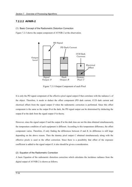
Section 7 Overview of Processing Algorithms7.2.2.2 AVNIR-2(1) Basic Concept of the Radiometric Distortion CorrectionFigure 7.2-3 shows the output component of AVNIR-2 at the observation.PD SignalPD Dark CurrentOutputLevelCCD DarkCurrrentElectricalOffsetSignalOutput ODarkOutput BDummyPixel CFigure 7.2-3 Output Component of each PixelIt is only the PD signal component of the effective pixel signal output O that correlates with the radiance L ofthe object. Therefore, it needs to deduct the offset component (PD dark current, CCD dark current andelectrical offset) from the signal output O when the radiometric correction is performed. Since this offsetcomponent is the same as the output B at the dark, the PD signal output can be determined by deducting theoutput B at the dark from the signal output O in theory.However, since the signal output O and the output B at the dark time are not the data obtained simultaneously,the temperature condition of each equipment is different. According to this temperature difference, the offsetcomponent varies. Therefore, if only finding the differences between O and B, its difference is still largedepending on the above reason. Then the dummy pixel output C obtained simultaneously along with theeffective pixels is used in the offset correction. Since there is a possibility that offset of the exposurecoefficient is added to the signal output O, it also should be given a consideration.(2) Equation of the Radiometric CorrectionA basic Equation of the radiometric distortion correction which calculates the incidence radiance from thedigital output of AVNIR-2 is shown as follows.7-14
<strong>ALOS</strong> <strong>Data</strong> <strong>Users</strong> <strong>Handbook</strong>1L = ⋅′α NL αR{( O − B − B − C ) − ( B − B′− C )}Equation 7.2-7Where,−2 −1−1L: Incidence radiance [ W ⋅ m ⋅ sr ⋅ μ m ]−2 −1−1R: Equipment sensitivity [ DN / ( W ⋅ m ⋅ sr ⋅ μ m )]−2 −1−1O: Signal output digital value [ DN / ( W ⋅ m ⋅ sr ⋅ μ m )]C: Dummy pixel output mean value at the time when the signal output value O is obtained [ DN ]B α : Offset of the exposure coefficient pulse at the time when the signal output value O is obtained[ DN ]B NL : Non-linear offset of output to the incidence radiance [ DN ]B: Output digital value at the dark [ DN ]C': Dummy pixel output mean value at the time when the output value B at the dark is obtainedDN[ ]B α ': Offset of the exposure coefficient pulse at the time when the output value B at the dark isobtained [ DN ]The detail each parameter expressed in the above expression is described as follows.(3) Radiometrically Corrected ProcessingWhen the radiometric model equation is expressed byx − b − cy = , calculate the correction coefficientacorresponding to ‘a’, ‘b’, ‘c’, and the radiometric correction is carried out. Where, ‘x’ is defined as anuncorrected input value before performing the radiometric correction. ‘y’ is defined as a radiometricallycorrected output value for every band and pixel number.a) Calculation of the correction coefficient ‘a’‘a’ is composed of the reference sensitivity, the pixel-to-pixel sensitivity deviation, the normalized exposurecoefficient, fluctuation of reflection rate of the pointing mirror, and sensitivity correction coefficient. It iscalculated based on the encoder data in the TT&C system telemetry data, the Detector temperature, Detectormodule temperature, and Signal Processor temperature.a = A( j,k,g ) ⋅ D( i, j,k,g ) ⋅ I( a, j,g ) ⋅ P( i, j, θ ) ⋅ K( i, j,k,g,T ,T ,T ) Equation 7.2-8DPRESPWhere, K( i, j,k,g,TD ,TPRE,TSP) is sensitivity correction coefficient.b) Calculation of the correction coefficient ‘b’‘b’ is composed of the offset level and the PD dark current. It is calculated based on the Detector temperaturein the TT&C System telemetry data for every band and pixel number.7-15


![4.12.2a_Tibet_Wu Guoxiong Tibet-CEOP.ppt[]](https://img.yumpu.com/35802437/1/190x135/4122a-tibet-wu-guoxiong-tibet-ceopppt.jpg?quality=85)