ALOS Data Users Handbook
ALOS Data Users Handbook
ALOS Data Users Handbook

You also want an ePaper? Increase the reach of your titles
YUMPU automatically turns print PDFs into web optimized ePapers that Google loves.
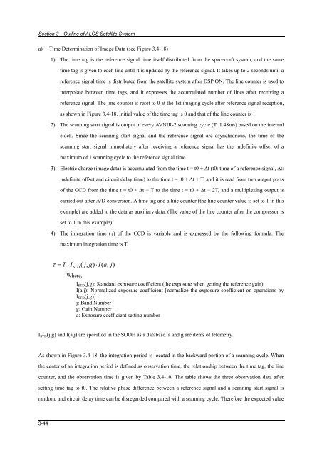
Section 3 Outline of <strong>ALOS</strong> Satellite Systema) Time Determination of Image <strong>Data</strong> (see Figure 3.4-18)1) The time tag is the reference signal time itself distributed from the spacecraft system, and the sametime tag is given to each line until it is updated by the reference signal. It takes up to 2 seconds until areference signal time is distributed from the satellite system after DSP ON. The line counter is used tointerpolate between time tags, and it expresses the accumulated number of lines after receiving areference signal. The line counter is reset to 0 at the 1st imaging cycle after reference signal reception,as shown in Figure 3.4-18. Initial value of the time tag is 0 and that of the line counter is 1.2) The scanning start signal is output in every AVNIR-2 scanning cycle (T: 1.48ms) based on the internalclock. Since the scanning start signal and the reference signal are asynchronous, the time of thescanning start signal immediately after receiving a reference signal has the indefinite offset of amaximum of 1 scanning cycle to the reference signal time.3) Electric charge (image data) is accumulated from the time t = t0 + Δt (t0: time of a reference signal, Δt:indefinite offset and circuit delay time) to the time t = t0 + Δt + T, and it is read from two output portsof the CCD from the time t = t0 + Δt + T to the time t = t0 + Δt + 2T, and a multiplexing output iscarried out after A/D conversion. A time tag and a line counter (the line counter value is set to 1 in thisexample) are added to the data as auxiliary data. (The value of the line counter after the compressor isset to 1 in this example).4) The integration time (τ) of the CCD is variable and is expressed by the following formula. Themaximum integration time is T.τ =T ⋅ I STD( j,g)⋅ I(a,j)Where,I STD (j,g): Standard exposure coefficient (the exposure when getting the reference gain)I(a,j): Normalized exposure coefficient [normalize the exposure coefficient on operations byI STD (j,g)]j: Band Numberg: Gain Numbera: Exposure coefficient setting numberI STD (j,g) and I(a,j) are specified in the SOOH as a database. a and g are items of telemetry.As shown in Figure 3.4-18, the integration period is located in the backward portion of a scanning cycle. Whenthe center of an integration period is defined as observation time, the relationship between the time tag, the linecounter, and the observation time is given by Table 3.4-10. The table shows the three observation data aftersetting time tag to t0. The relative phase difference between a reference signal and a scanning start signal israndom, and circuit delay time can be disregarded compared with a scanning cycle. Therefore the expected value3-44


![4.12.2a_Tibet_Wu Guoxiong Tibet-CEOP.ppt[]](https://img.yumpu.com/35802437/1/190x135/4122a-tibet-wu-guoxiong-tibet-ceopppt.jpg?quality=85)