10 table saw - Grizzly Industrial Inc.
10 table saw - Grizzly Industrial Inc.
10 table saw - Grizzly Industrial Inc.

Create successful ePaper yourself
Turn your PDF publications into a flip-book with our unique Google optimized e-Paper software.
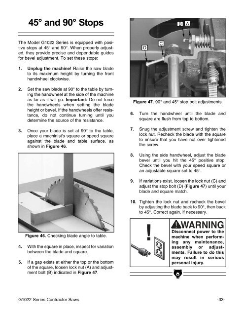
45° and 90° StopsBAThe Model G<strong>10</strong>22 Series is equipped with positivestops at 45° and 90°. When properly adjusted,they provide precise and dependable guidesfor bevel adjustment. To set these stops:1. Unplug the machine! Raise the <strong>saw</strong> bladeto its maximum height by turning the fronthandwheel clockwise.DC2. Set the <strong>saw</strong> blade at 90° to the <strong>table</strong> by turningthe handwheel at the side of the machineas far as it will go. Important: Do not forcethe handwheels when setting the bladeheight or bevel. If the handwheels offer resistance,do not continue turning until youdetermine the source of the resistance.3. Once your blade is set at 90° to the <strong>table</strong>,place a machinist's square or speed squareagainst the blade and <strong>table</strong> surface, asshown in Figure 46.Figure 47. 90° and 45° stop bolt adjustments.6. Turn the handwheel until the blade andsquare are flush from top to bottom.7. Snug the adjustment screw and tighten thelock nut. Recheck the blade with the squareto ensure that you have not over tightenedthe screw.8. Using the side handwheel, adjust the bladebevel until you hit the 45° positive stop.Check the bevel with your speed square oran adjus<strong>table</strong> square set to 45°.9. If variations exist, loosen the lock nut (C) andadjust the stop bolt (D) (Figure 47) until yourblade and square match.<strong>10</strong>. Tighten the lock nut and recheck the bevelby adjusting the blade back to 90°, then backto 45°. Correct again, if necessary.Figure 46. Checking blade angle to <strong>table</strong>.4. With the square in place, inspect for variationbetween the blade and square.5. If a gap exists at either the top or the bottomof the square, loosen lock nut (A) and adjustmentbolt (B) indicated in Figure 47.!Disconnect power to themachine when performingany maintenance,assembly or adjustments.Failure to do thismay result in seriouspersonal injury.G<strong>10</strong>22 Series Contractor Saws -33-