10 table saw - Grizzly Industrial Inc.
10 table saw - Grizzly Industrial Inc.
10 table saw - Grizzly Industrial Inc.

You also want an ePaper? Increase the reach of your titles
YUMPU automatically turns print PDFs into web optimized ePapers that Google loves.
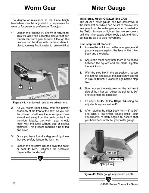
Worm GearMiter GaugeThe degree of resistance at the blade heighthandwheel can be adjusted to compensate forwear or for personal preference. To adjust:1. Loosen the lock nut (A) shown in Figure 48.This will allow the eccentric sleeve that surroundsthe worm gear to turn. Although thisprocess can be done with the handwheel inplace, you may find it easier to remove it first.Initial Step, Model G<strong>10</strong>22ZF and ZFX:The ZF/ZFX miter gauge has two setscrews inthe miter slot bar which can be set to remove anyfree play from the miter gauge when inserted inthe T-slot. Loosen or tighten the two setscrewsuntil the miter gauge slides freely back and forth,but has no side-to-side movement.Next step for all models:1. Loosen the lock knob on the miter gauge andplace a square against the face of the miterbody and the blade.AB2. Adjust the miter body until there is no spacebetween the square and the blade. Tightenthe lock knob.3. With the stop link in the up position, loosenthe jam nut and adjust the stop screw shownin Figure 49 until it is seated against the stoplink.4. Now loosen the setscrew on the left frontside of the miter bar, adjust the pointer to 90˚and retighten the setscrew.Figure 48. Handwheel resistance adjustment.2. As you watch from below, twist the pointerassembly at the front of the <strong>saw</strong>. As you turnthe pointer, you’ll see the worm gear movetoward and away from the teeth on the fronttrunnion. Ideally, the worm gear shouldmesh with the teeth without slop or excesstightness. This process requires a bit of trialand error.5. To adjust to 45˚, follow Steps 1-4 using anadjus<strong>table</strong> square set to 45˚.6. After rotating the miter body from 45˚ to 90˚and back a few times, double check youradjustments at both angles to assure thatyou have accurately set your miter gauge.3. Once you have found a degree of tightnessthat you prefer, tighten the lock nut.4. Loosen the setscrew (B) and pivot the pointerback to zero. Retighten the setscrew.Replace the handwheel.Jam NutStop LinkStop ScrewFigure 49. Miter gauge adjustment points.-34-G<strong>10</strong>22 Series Contractor Saws