
You also want an ePaper? Increase the reach of your titles
YUMPU automatically turns print PDFs into web optimized ePapers that Google loves.
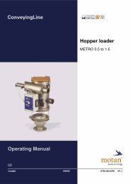
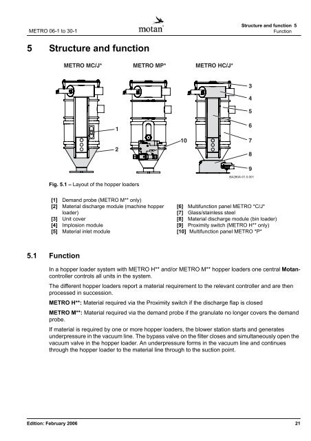
METRO 06-1 to 30-1Structure and function 5Function5 Structure and functionFig. 5.1 – Layout of the hopper <strong>loader</strong>s[1] Demand probe (METRO M** only)[2] Material discharge module (machine hopper<strong>loader</strong>)[3] Unit cover[4] Implosion module[5] Material inlet module[6] Multifunction panel METRO *C/J*[7] Glass/stainless steel[8] Material discharge module (bin <strong>loader</strong>)[9] Proximity switch (METRO H** only)[10] Multifunction panel METRO *P*5.1 FunctionIn a hopper <strong>loader</strong> system with METRO H** and/or METRO M** hopper <strong>loader</strong>s one central Motancontrollercontrols all units in the system.The different hopper <strong>loader</strong>s report a material requirement to the relevant controller and are thenprocessed in succession.METRO H**: Material required via the Proximity switch if the discharge flap is closedMETRO M**: Material required via the demand probe if the granulate no longer covers the demandprobe.If material is required by one or more hopper <strong>loader</strong>s, the blower station starts and generatesunderpressure in the vacuum line. The bypass valve on the filter closes and simultaneously open thevacuum valve in the hopper <strong>loader</strong>. An underpressure forms in the vacuum line and continuesthrough the hopper <strong>loader</strong> to the material line through to the suction point.Edition: February 2006 21