SA03-01 (X Series) Installation Manual.pdf - Footprint Security
SA03-01 (X Series) Installation Manual.pdf - Footprint Security
SA03-01 (X Series) Installation Manual.pdf - Footprint Security

You also want an ePaper? Increase the reach of your titles
YUMPU automatically turns print PDFs into web optimized ePapers that Google loves.
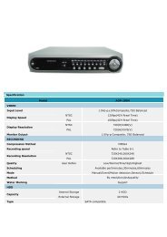
APPENDIX A:SECURITY SYSTEM INSTALLATION4 Wire Connectiona) b)External Trigger connections<strong>Security</strong>PanelArmed Zone 0V 12VExternal Trig inputTamperN.CRelayTrig PowerArmed 0V 12VTamperN.CRelayTrig PowerArmed 0V 12VInterfaceBoardDoor or windowswitch used asexternal trigger *2K2InterfaceBoardEnd of lineresistor* The external trigger input is set up for a normally o penswitch by default. This can be chan ged fo r a no rmallyclosed switch via the setup software..FIGURE 6 - SECURITY SYSTEM WIRING EXAMPLESBefore installing the camera to a security system it is recommended that users readthe ‘Choosing A Camera Location’ section (page 14) for more information aboutobtaining optimal quality images from the camera.To add an Xtern-Cam to an existing security system:1. Disconnect power to the security system, including the battery.2. Turn off the Camera and remove the battery.3. Remove the rear case of the Camera.4. Carefully plug in the Interface board to the Camera board and secure with 2 screwsat the top.5. Create a hole for the security wires in the rear case.If the camera is being installed outdoors then care should be taken to ensure that thecase’s weatherproof rating is preserved.6. Feed the security system wires through the hole and connect them to therespective terminals on the interface board using one of the reference diagrams inFigure 6The Xtern-cam is a battery operated device. Its battery life can be extended via its onboardrecharge circuitry by wiring to the 12Vdc power supply of an alarm system.However, if installed in a location where it regularly captures a high number of infra-redimages in short periods of time, the power consumption may exceed power recharge, causingthe battery to go flat. The camera will recharge the battery irrespective of its armed ordisarmed state.7. If the camera is to be triggered by an external source such as a door, window orgate, wire the external switch between 0V and the External trigger input on theinterface board’s screw terminal strip (see Figure 7). If required, it is possible to usethe Camera Setup software to disable the motion sensor and/or configure theexternal trigger’s normally closed/normally opened switch type.<strong>SA03</strong>-<strong>01</strong> (X SERIES) INSTALLATION MANUAL V1.0.1 (APRIL 2009) 31