Pobierz pełny numer 1/2010 S&E - Structure and Environment - Kielce
Pobierz pełny numer 1/2010 S&E - Structure and Environment - Kielce
Pobierz pełny numer 1/2010 S&E - Structure and Environment - Kielce
- No tags were found...

Create successful ePaper yourself
Turn your PDF publications into a flip-book with our unique Google optimized e-Paper software.
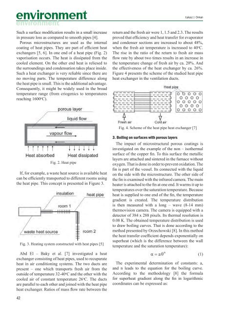
Łukasz J. OrmanSuch a surface modification results in a small increasein pressure loss as compared to smooth pipes [4].Porous microstructures are used as the internalcoating of heat pipes. They are part of efficient heatexchangers [5, 6]. In one end of a heat pipe (Fig. 2)vaporisation occurs. The heat is dissipated from thecooled element. On the other end heat is reliesed tothe surroundings <strong>and</strong> condensation takes place inside.Such a heat exchanger is very reliable since there areno moving parts. The temperature difference alongthe heat pipe is small. This is the additional advantage.Consequently, it might be widely used in the broadtemperature range (from criogenics to temperaturesreaching 1600 o C).return <strong>and</strong> the fresh air were 1, 1.5 <strong>and</strong> 2.3. The resultsproved that efficiency <strong>and</strong> heat transfer for evaporator<strong>and</strong> condenser sections are increased to about 48%,when the fresh air temperature is increased to 40 o C.The rise in the ratio of the return to fresh air massflow rate by about two times results in an increase inthe temperature change of fresh air by ca. 20%. Andthe effectiveness of the heat exchanger by ca. 26%.Figure 4 presents the scheme of the studied heat pipeheat exchanger in the ventilation ducts.Fig. 4. Scheme of the heat pipe heat exchanger [7]Fig. 2. Heat pipeIf, for example, a waste heat source is available heatcan be efficiently transported to different rooms usingthe heat pipe. This concept is presented in Figure 3.Fig. 3. Heating system constructed with heat pipes [5]Abd El – Baky et al. [7] investigated a heatexchanger consisting of heat pipes, used to recuparateheat in air conditioning systems. The two ducts arepresent – one which transports fresh air from theoutside of temperature 32-40 o C <strong>and</strong> the other with thecooled air of constant temperature 26 o C. The ductsare parallel to each other <strong>and</strong> joined with the heat pipeheat exchanger. Ratios of mass flow rate between the3. Boiling on surfaces with porous layersThe impact of microstructural porous coatings isinvestigated on the example of the non – isothermalsurface of the copper fin. To this surface the metalliclayers are attached <strong>and</strong> sintered in the furnace withoutoxygen. That is done in order to prevent oxidation. Thefin is part of the vessel. Its connected with the liquidon the side with the microstructure. The other side ofthe fin is examined with the infrared camera. The mainheater is attached to the fin at one end. It warms it up totemperatures over the saturation temperature. Becauseheat is supplied to one end of the fin, the temperaturegradient is created. The temperature distributionis then measured with a long – wave (8-14 mm)thermovision camera. The camera is equipped with adetector of 384 x 288 pixels. Its thermal resolution is0.08 K. The obtained temperature distribution is usedto draw boiling curves. That is done according to themethod presented by Orzechowski [8]. In this methodthe heat transfer coefficient depends exponentially onsuperheat (which is the difference between the walltemperature <strong>and</strong> the saturation temperature):(1)The experimental determination of constants: a,<strong>and</strong> n leads to the equation for the boiling curve.According to the methodology [8] the formulafor superheat gradient along the fin in logarithmiccoordinates can be expressed as:42