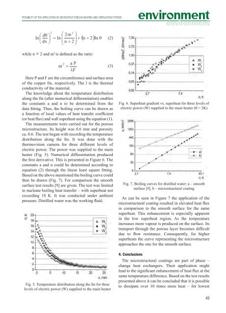
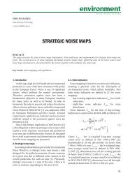
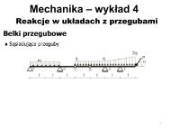
POSSIBILITY OF THE APPLICATION OF MICROSTRUCTURES IN HEATING AND VENTILATION SYSTEMS(2)while n2 <strong>and</strong> m 2 is defined as the ratio:(3)Here P <strong>and</strong> F are the circumference <strong>and</strong> surface areaof the copper fin, respectively. The l is the thermalconductivity of the material.The knowledge about the temperature distributionalong the fin (after <strong>numer</strong>ical differentiation) enablesthe constants a <strong>and</strong> n to be determined from thedata fitting. Thus, the boiling curve can be drawn asa function of local values of heat transfer coefficient(or heat flux) <strong>and</strong> wall superheat using the equation (1).The measurements were carried out for the porousmicrostructure. Its height was 0.6 mm <strong>and</strong> porosityca. 0.6. The test began with recording the temperaturedistribution along the fin. It was done with thethermovision camera for three different levels ofelectric power. The power was supplied to the mainheater (Fig. 5). Numerical differentiation producedthe first derivative. This is presented in Figure 6. Theconstants a <strong>and</strong> n could be determined according toequation (2) through the linear least square fitting.Based on the above mentioned the boiling curve couldthen be drawn (Fig. 7). For comparison the smoothsurface test results [9] are given. The test was limitedto nucleate boiling heat transfer – with superheat notexceeding 18 K. It was conducted under ambientpressure. Distilled water was the working fluid.Fig. 5. Temperature distribution along the fin for threelevels of electric power (W) supplied to the main heaterFig. 6. Superheat gradient vs. superheat for three levels ofelectric power (W) supplied to the main heater (q > 2K)Fig. 7. Boiling curves for distilled water: a – smoothsurface [9], b – microstructural coatingAs can be seen in Figure 7 the application of themicrostructural coating resulted in elevated heat fluxin comparison to the smooth surface for the samesuperheat. This enhancement is especially apparentin the low superheat region. As the temperatureincreases more vapour is produced on the surface. Itstransport through the porous layer becomes difficultdue to flow resistance. Consequently, for highersuperheats the curve representing the microstructureapproaches the one for the smooth surface.4. ConclusionsThe microstructural coatings are part of phase –change heat exchangers. Their application mightlead to the significant enhancement of heat flux at thesame temparature difference. Based on the test resultspresented above it can be concluded that it is possibleto dissipate over 10 times more heat – for lowest43
Łukasz J. Ormansuperheats – if porous layers are used, as compared tosmooth reference surface. Heat exchangers producedwith microstructures could be working with differentfluids. More tests are needed to determine optimalgeometrical <strong>and</strong> material properties of different kindsof porous layers. They will ensure the maximal heatflux to be dissipated. Thus, the design guidelinescould be proposed for the production of such heatexchangers.References[1] Webb R.L. (1981): The evolution of enhanced surfacegeometries for nucleate boiling, Heat TransferEngineering, Vol. 2, pp. 46-69.[2] Manglik R.M. (2003): Heat Transfer Enhancement, inHeat Transfer H<strong>and</strong>book, ed. Bejan A., Kraus A.D.,John Wiley&Sons Inc.[3] Gottzmann C.F., Wulf J.B., O’Neill P. (1971): Theory<strong>and</strong> application of high performance boiling surfacesto components of absorption cycle air conditioners,Proc. Conf. Natural Gas. Res. <strong>and</strong> Techn., Chicago,pp. 1-14.[4] Thome J.R. (2004): Engineering Data Book III,Wolverine Tube.[5] Silverstein C.C. (1992): Design <strong>and</strong> technology of heatpipes for cooling <strong>and</strong> heat exchange, Washington.[6] Ochterbeck J.M. (2003): Heat Pipes, in Heat TransferH<strong>and</strong>book, Bejan A., Kraus A.D. (ed), Wiley John &Sons Inc.[7] Abd El – Baky M.A., Mohamed M.M. (2007): Heat pipeheat exchanger for heat recovery in air conditioning,Applied Thermal Engineering, Vol. 27, pp. 795-801.[8] Orzechowski T. (2003): Wymiana ciepła przy wrzeniu nażebrach z mikropowierzchnią strukturalną, Monografia,Wydawnictwo Politechniki Świętokrzyskiej, <strong>Kielce</strong>.[9] Orman Ł.J. (2008): Nucleate boiling heat transfer ona smooth surface of a fin, Proc of XII Int. Symposium„Heat Transfer <strong>and</strong> Renewable Sources of Energy”,Szczecin, pp. 363-369.Łukasz J. OrmanMożliwości zastosowania mikropowierzchnistrukturalnych w ogrzewnictwie i wentylacji1. WstępObecnie szerokie zainteresowanie wzbudzają wysoceefektywne wymienniki ciepła. Szczególnie interesującesą te, które pracują przy zmianie fazy czynnika,ponieważ umożliwiają odbieranie znacznychgęstości strumienia ciepła. Są one powszechnie stosowanem.in. w chłodnictwie czy klimatyzacji. Potrzebaodbierania coraz większych strumieni ciepładoprowadziła do odkrycia pokryć intensyfikującychwymianę ciepła, które nakłada się na powierzchniewymienników. Takie mikrostruktury wytwarza się zespieczonych proszków metalicznych, siatek czy włókienlub jako mikrożebra lub mikrowgłębienia. Mogąbyć one stosowane w przypadku zarówno kondensacjijak i wrzenia.2. Mikropowierzchnie strukturalne w ogrzewnictwiei wentylacjiPierwszą pracą dotyczącą intensyfikacji wymianyciepła przy wrzeniu były badania Jakoba i Fritzaw 1931 r., w których wykazali, że zwiększenie chropowatościpowierzchni grzejnej prowadzi do zwiększeniailości odbieranego ciepła. Zjawisko to nie byłojednak obiektem większego zainteresowania. Dopierolata 1955-1965 zaowocowały opracowaniem strukturintensyfikujących wymianę ciepła przy wrzeniu.Pierwszą taką strukturę opatentowano w 1968 r. [1].Mikropowierzchnie strukturalne mogą być stosowanew wielu gałęziach przemysłu. Gottzmanni in. [3] opisali zastosowanie powierzchni High Fluxw parownikach klimatyzatorów wykorzystującychcykl absorbcyjny amoniaku. Przeprowadzone doświadczeniaprzy wrzeniu roztworu 16-17% amoniakudowodzą, że możliwe jest dwukrotne zwiększeniegęstości strumienia ciepła przy jednoczesnej redukcjiróżnicy temperatury o około 1 K.Wymienniki rurowe intensyfikujące wymianęciepła są powszechnie stosowane w chłodnictwiei klimatyzacji. Powodują zmniejszenie wymiarówurządzeń i wymaganej ilości płynów chłodniczychw wymienniku. W przypadku zastosowań chłodniczychi klimatyzacyjnych stosuje się obecnie ruryz wewnętrznymi mikrożebrami [4].Powierzchnie porowate stosowane są jako wypełnienierur ciepła, stanowiących element efektywnychwymienników ciepła [5, 6]. W rurze ciepła można44