Minnegang Creek Flood Study Report - Wollongong City Council
Minnegang Creek Flood Study Report - Wollongong City Council
Minnegang Creek Flood Study Report - Wollongong City Council
- No tags were found...
You also want an ePaper? Increase the reach of your titles
YUMPU automatically turns print PDFs into web optimized ePapers that Google loves.
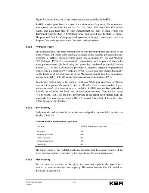
Figure 5-6 shows the extent of the stormwater system modelled in RatHGL.RatHGL models peak flows at a point for a given storm frequency. The stormwaterpipe system was modelled for the 1%, 2%, 5%, 20%, 50% and 100% AEP designevents. The peak local flow in each subcatchment for each of these events wasdetermined from the RAFTS hydrologic model and entered into the RatHGL model.The peak total flow for <strong>Minnegang</strong> <strong>Creek</strong> upstream of the piped system was entered asthe peak flow at the upstream end of the piped drainage system.5.12.1 Hydraulic lossesThe configuration of the pipes entering each pit was determined from the survey of thepiped system. Pit losses were generally assigned using standard pit configurationspresented in RatHGL, which are based on pit loss calculations by Hare and Missouri(WP Software, 1996). For non-standard configurations, such as pits with three inletpipes, pit losses were calculated using the “generalised manhole loss equation” optionin RatHGL. The loss is evaluated as per Hare/O’Loughlin’s equation for generalisedconnectivity at a manhole (WP Software, 1996). Losses were also specified manuallyfor the headwall at the upstream end of the <strong>Minnegang</strong> branch, based on an entranceloss coefficient (k e ) of 0.5 (Concrete Pipe Association of Australasia, 1991).To estimate friction loss in the pipes, a Colebrook White pipe roughness of 0.6mmwas used to represent the concrete pipes in all links. This is a conservative figure,representative of a pipe network in poor condition. RatHGL uses the Darcy-WeisbachFormula to calculate the head loss in each pipe resulting from friction losses(WP Software, 1996). For the pipe downstream of the grated pit in Barina Park, aninter-nodal loss was also specified in RatHGL to model the effect of the orifice platewithin the pipe at this location.5.12.2 Inlet capacityEach manhole and junction in the model was assigned a constant inlet capacity, aslisted in Table 5-6.Table 5-6 RatHGL manhole inlet capacitiesInlet typeRatHGL Inlet Capacity (m 3 /sec)Kerb inlet 0.1Kerb and grate inlet 0.15Grated sag inlet 0.2Concrete/steel cover 0.0Junction pit 0.0The initial results of the RatHGL modelling indicated that the capacity of most of thepiped drainage system is restricted by the capacities of the stormwater inlets.5.12.3 Pipe capacityTo determine the capacity of the pipes, the stormwater pits in the system wereassumed to have an unlimited inlet capacity. The results from the RatHGL model arediscussed in Section 6.2.SV8507-D0-001 Rev 2 5-3418/10/02


