Prof. Dr Jan Pajak THE NEW ZEALAND EXPLOSION OF ... - Totalizm
Prof. Dr Jan Pajak THE NEW ZEALAND EXPLOSION OF ... - Totalizm
Prof. Dr Jan Pajak THE NEW ZEALAND EXPLOSION OF ... - Totalizm
- No tags were found...

Create successful ePaper yourself
Turn your PDF publications into a flip-book with our unique Google optimized e-Paper software.
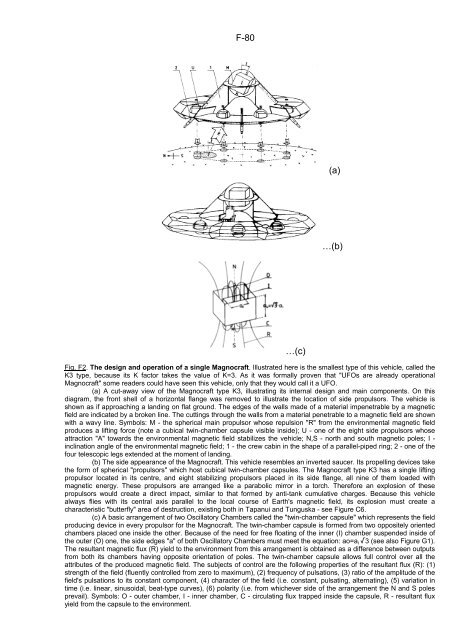
F-80(a)…(b)…(c)Fig. F2. The design and operation of a single Magnocraft. Illustrated here is the smallest type of this vehicle, called theK3 type, because its K factor takes the value of K=3. As it was formally proven that "UFOs are already operationalMagnocraft" some readers could have seen this vehicle, only that they would call it a UFO.(a) A cut-away view of the Magnocraft type K3, illustrating its internal design and main components. On thisdiagram, the front shell of a horizontal flange was removed to illustrate the location of side propulsors. The vehicle isshown as if approaching a landing on flat ground. The edges of the walls made of a material impenetrable by a magneticfield are indicated by a broken line. The cuttings through the walls from a material penetrable to a magnetic field are shownwith a wavy line. Symbols: M - the spherical main propulsor whose repulsion "R" from the environmental magnetic fieldproduces a lifting force (note a cubical twin-chamber capsule visible inside); U - one of the eight side propulsors whoseattraction "A" towards the environmental magnetic field stabilizes the vehicle; N,S - north and south magnetic poles; I -inclination angle of the environmental magnetic field; 1 - the crew cabin in the shape of a parallel-piped ring; 2 - one of thefour telescopic legs extended at the moment of landing.(b) The side appearance of the Magnocraft. This vehicle resembles an inverted saucer. Its propelling devices takethe form of spherical "propulsors" which host cubical twin-chamber capsules. The Magnocraft type K3 has a single liftingpropulsor located in its centre, and eight stabilizing propulsors placed in its side flange, all nine of them loaded withmagnetic energy. These propulsors are arranged like a parabolic mirror in a torch. Therefore an explosion of thesepropulsors would create a direct impact, similar to that formed by anti-tank cumulative charges. Because this vehiclealways flies with its central axis parallel to the local course of Earth's magnetic field, its explosion must create acharacteristic "butterfly" area of destruction, existing both in Tapanui and Tunguska - see Figure C6.(c) A basic arrangement of two Oscillatory Chambers called the "twin-chamber capsule" which represents the fieldproducing device in every propulsor for the Magnocraft. The twin-chamber capsule is formed from two oppositely orientedchambers placed one inside the other. Because of the need for free floating of the inner (I) chamber suspended inside ofthe outer (O) one, the side edges "a" of both Oscillatory Chambers must meet the equation: ao=a i /3 (see also Figure G1).The resultant magnetic flux (R) yield to the environment from this arrangement is obtained as a difference between outputsfrom both its chambers having opposite orientation of poles. The twin-chamber capsule allows full control over all theattributes of the produced magnetic field. The subjects of control are the following properties of the resultant flux (R): (1)strength of the field (fluently controlled from zero to maximum), (2) frequency of pulsations, (3) ratio of the amplitude of thefield's pulsations to its constant component, (4) character of the field (i.e. constant, pulsating, alternating), (5) variation intime (i.e. linear, sinusoidal, beat-type curves), (6) polarity (i.e. from whichever side of the arrangement the N and S polesprevail). Symbols: O - outer chamber, I - inner chamber, C - circulating flux trapped inside the capsule, R - resultant fluxyield from the capsule to the environment.


![[1/4p]: PDF - Totalizm](https://img.yumpu.com/45003232/1/184x260/1-4p-pdf-totalizm.jpg?quality=85)


![[1/4p]: PDF - Totalizm](https://img.yumpu.com/39351336/1/184x260/1-4p-pdf-totalizm.jpg?quality=85)