- Page 1 and 2:
MIMO and Smart Antennasfor 3G and 4
- Page 3 and 4:
5 Small Cells and HetNet Deployment
- Page 5 and 6:
5) Smart antennas provide the next
- Page 7 and 8:
toward the ground where the mobile
- Page 9 and 10:
could then be tailored using mechan
- Page 11 and 12:
Figure 6 - Antenna technology curre
- Page 13 and 14:
1.3 INTEGRATED RADIO/ANTENNAFigure
- Page 15 and 16:
Figure 10 - Link budget comparison
- Page 17 and 18:
1.4 ACTIVE ANTENNA SYSTEM (AAS) TEC
- Page 19 and 20:
and combinations of carriers that c
- Page 21 and 22:
example, a rural base station with
- Page 23 and 24:
eamwidth is typically fixed if area
- Page 25 and 26:
for flat rural scenarios with large
- Page 27 and 28:
Figure 22, for unprocessed and fitt
- Page 29 and 30:
Note that this is likely a general
- Page 31 and 32:
carrier frequency) limited uplink t
- Page 33 and 34:
These transmission modes are implem
- Page 35 and 36:
Code Book 1 Layer 2 Layers0 1√2 1
- Page 37 and 38:
codebook entry 2 will reduce interf
- Page 39 and 40:
Trans. ModeAntennaConfig. Figure De
- Page 41 and 42:
It is important to note that the ga
- Page 43 and 44:
5 inputs forming the five beams sho
- Page 45 and 46:
Figure 32 - Downlink bit rate (left
- Page 47 and 48:
system simulation CDF for the anten
- Page 49 and 50:
Figure 36 - Calibration network blo
- Page 51 and 52:
smaller allocation. MU-MIMO transmi
- Page 53 and 54:
1D Reconfigurable beam (RET)[tiltin
- Page 55 and 56:
3.3 COMPARISON OF RET, 2D, AND 3D R
- Page 57 and 58:
3.5 NETWORK OPTIMIZATION VERSUS LOA
- Page 59 and 60: Figure 40 - Distribution of the ant
- Page 61 and 62: • In this case, reconfigurable be
- Page 63 and 64: Figure 43 - Typical cell site showi
- Page 65 and 66: 4.2 CURRENT DEPLOYMENTSOne operator
- Page 67 and 68: Figure 46 - Common monopole during
- Page 69 and 70: Figure 48 - Mast with 11 operators
- Page 71 and 72: Figure 50 - Antenna mount with Remo
- Page 73 and 74: (a) (b) (c)Figure 52 - Small cell s
- Page 75 and 76: 6 MISCELLANEOUS COMMERCIAL AND DEPL
- Page 77 and 78: Figure 54AFigure 54BFigure 54 — H
- Page 79 and 80: The widely used 65º azimuth antenn
- Page 81 and 82: Figure 59 — Mathematical results
- Page 83 and 84: Recall that the new rules of thumb
- Page 85 and 86: 300∑P60SPR(%) =60P∑300Undesired
- Page 87 and 88: --Co-Polarization--Cross-Polarizati
- Page 89 and 90: 6.2.2 EFFECTS OF INCORRECT ANTENNA
- Page 91 and 92: any third order intermodulation pro
- Page 93 and 94: A RRH, also known as a Remote Radio
- Page 95 and 96: delays of each transmit path. These
- Page 97 and 98: equired at the antenna. In addition
- Page 99 and 100: Figure 72 - Photograph of the const
- Page 101 and 102: These cables, being a stranded cons
- Page 103 and 104: 6.6.5 ADVANTAGES OF REMOTE FIBER FE
- Page 105 and 106: Figure 79 - Diplexer.Figure 80 - Tr
- Page 107 and 108: Figure 81 - Hybrid combiningcable l
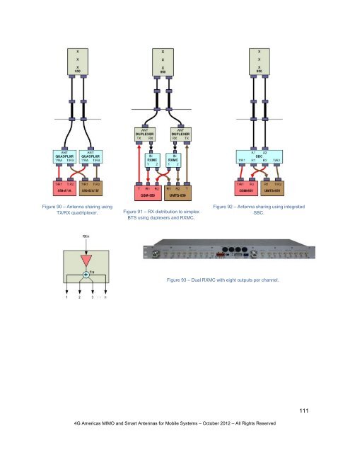
- Page 109: ports. Integrated duplexers route t
- Page 113 and 114: 6.7.13 CONFIGURATIONSThe key elemen
- Page 115 and 116: 6.8 INDOOR DISTRIBUTED ANTENNA SYST
- Page 117 and 118: een proven by experiment that a spa
- Page 119 and 120: 2600 6 to 9 --Table 7 - Link budget
- Page 121 and 122: Figure 107 - Shannon upper limit ca
- Page 123 and 124: achieve MIMO performance on par wit
- Page 125 and 126: It is evident from the trial that M
- Page 127 and 128: Figure 112 - Example antennas from
- Page 129 and 130: 1st Upper Sidelobe Level of the 1st
- Page 131 and 132: H/V TrackingDiscrimination between
- Page 133 and 134: Digital RF converterto LNAPAdigital
- Page 135 and 136: 27 Section 7.1 of 3GPP Section 7.1
- Page 137 and 138: 51 IST-4-027756 WINNER, D1.1.2 V1.1