MIMO and Smart Antennas for Mobile Broadband ... - 4G Americas
MIMO and Smart Antennas for Mobile Broadband ... - 4G Americas
MIMO and Smart Antennas for Mobile Broadband ... - 4G Americas

Create successful ePaper yourself
Turn your PDF publications into a flip-book with our unique Google optimized e-Paper software.
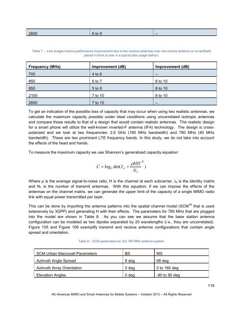
2600 6 to 9 --Table 7 – Link budget receive per<strong>for</strong>mance improvement due to two receive antennas over one receive antenna on a h<strong>and</strong>heldplaced in front of user in a typical data usage fashion.Frequency (MHz) Improvement (dB) Improvement (dB)700 4 to 6 --850 5 to 7 8 to 10950 5 to 8 8 to 102100 7 to 10 8 to 102600 7 to 10 --To get an indication of the possible loss of capacity that may occur when using two realistic antennas, wecalculate the maximum capacity possible under ideal conditions using uncorrelated isotropic antennas<strong>and</strong> compare those results to that of a design that would contain realistic antennas. The realistic design<strong>for</strong> a smart phone will utilize the well-known inverted-F antenna (IFA) technology. The design is crosspolarized<strong>and</strong> we look at two frequencies: 2.6 GHz (190 MHz b<strong>and</strong>width) <strong>and</strong> 780 MHz (40 MHzb<strong>and</strong>width). These are two prominent LTE frequency b<strong>and</strong>s. In this study, we do not take into accountthe effects of the head <strong>and</strong> h<strong>and</strong>s.To measure the maximum capacity we use Shannon’s generalized capacity equation:C = log 2det( INρHH+NTH)Where ρ is the average signal-to-noise ratio, H is the channel at each subcarrier, I N is the identity matrix<strong>and</strong> N T is the number of transmit antennas. With this equation, if we can impose the effects of theantennas on the channel matrix, we can generate the upper limit of the capacity of a single <strong>MIMO</strong> radiolink with equal power transmitted per layer.This can be done by importing the antenna patterns into the spatial channel model (SCM 59 that is usedextensively by 3GPP) <strong>and</strong> generating H with their effects. The parameters <strong>for</strong> 780 MHz that are pluggedinto the model are shown in Table 8. As you can see we assume that the base station antennaconfiguration can be modeled as two dipoles separated by 20 wavelengths (i.e., they are uncorrelated).Figure 105 <strong>and</strong> Figure 106 exemplify transmit <strong>and</strong> receive antenna configurations that contain anglespread <strong>and</strong> orientation.Table 8 – SCM parameters <strong>for</strong> 2x2 780 MHz antenna system.SCM Urban Macrocell Parameters BS MSAzimuth Angle Spread 8 deg 68 degAzimuth Array Orientation 0 deg 0 to 180 degElevation Angles 0 deg -90 to 90 deg119<strong>4G</strong> <strong>Americas</strong> <strong>MIMO</strong> <strong>and</strong> <strong>Smart</strong> <strong>Antennas</strong> <strong>for</strong> <strong>Mobile</strong> Systems – October 2012 – All Rights Reserved