MIMO and Smart Antennas for Mobile Broadband ... - 4G Americas
MIMO and Smart Antennas for Mobile Broadband ... - 4G Americas
MIMO and Smart Antennas for Mobile Broadband ... - 4G Americas

You also want an ePaper? Increase the reach of your titles
YUMPU automatically turns print PDFs into web optimized ePapers that Google loves.
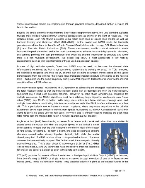
These transmission modes are implemented through physical antennas described further in Figure 29later in the section.Beyond the single antenna or beam<strong>for</strong>ming array cases diagrammed above, the LTE st<strong>and</strong>ard supportsMultiple Input Multiple Output (<strong>MIMO</strong>) antenna configurations as shown on the right of Figure 25. Thisincludes Single User (SU-<strong>MIMO</strong>) protocols using either open loop or closed loop modes as well astransmit diversity <strong>and</strong> Multi-User <strong>MIMO</strong> (MU-<strong>MIMO</strong>). In the closed loop <strong>MIMO</strong> mode, the terminalsprovide channel feedback to the eNodeB with Channel Quality In<strong>for</strong>mation through CQI, Rank Indications(RI) <strong>and</strong> Precoder Matrix Indications (PMI). These mechanisms enable channel estimation whichimproves the peak data rates, <strong>and</strong> is the most commonly used scheme in current deployments. However,this scheme provides the best per<strong>for</strong>mance only when the channel in<strong>for</strong>mation is accurate <strong>and</strong> whenthere is a rich multipath environment. So closed loop <strong>MIMO</strong> is most appropriate in low mobilityenvironments such as with fixed terminals or those used at pedestrian speeds.In case of high vehicular speeds, Open Loop <strong>MIMO</strong> may be used, but because the channel statein<strong>for</strong>mation is not timely, the PMI is not considered reliable <strong>and</strong> is typically not used. In TDD networks,the channel is reciprocal <strong>and</strong> thus the DL channel can be more accurately known based on the uplinktransmissions from the terminal (the <strong>for</strong>ward link’s multipath channel signature is the same as the reverselink’s – both paths use the same frequency block), so <strong>MIMO</strong> improves TDD networks under wider channelconditions than in FDD networks.One may visualize spatial multiplexing <strong>MIMO</strong> operation as subtracting the strongest received stream fromthe total received signal so that the next strongest signal can be decoded <strong>and</strong> then the next strongest,somewhat like a multi-user detection scheme. However, to solve these simultaneous equations <strong>for</strong>multiple unknowns, the <strong>MIMO</strong> algorithms must have relatively large Signal to Interference plus Noiseratios (SINR), say 15 dB or better. With many users active in a base station’s coverage area, <strong>and</strong>multiple base stations contributing interference to adjacent cells, the SINR is often in the realm of a fewdB. This is particularly true <strong>for</strong> frequency reuse 1 systems, where only users very close to the cell siteexperience SINRs high enough to benefit from spatial multiplexing SU-<strong>MIMO</strong>. Consequently, SU-<strong>MIMO</strong>works to serve the single user (or few users) very well, <strong>and</strong> is primarily used to increase the peak datarates rather than the median data rate in a network operating at full capacity.Angle of Arrival (AoA) beam<strong>for</strong>ming schemes <strong>for</strong>m beams which work well when the base station isclearly above the clutter <strong>and</strong> when the angular spread of the arrival is small,corresponding to users that are well localized in the field of view of the sector;in rural areas, <strong>for</strong> example. To <strong>for</strong>m a beam, one uses co-polarized antennaelements spaced rather closely together, typically λ/2, while the spatialdiversity required of <strong>MIMO</strong> requires either cross-polarized antenna columns orcolumns that are relatively far apart. The farther apart, the more path diversitythey will couple to. This is often about 10 wavelengths (1.5m or 5’ at 2 GHz).This is why most 2G <strong>and</strong> 3G tower sites have two receive antennas located atfar ends of the sector’s plat<strong>for</strong>m as seen in the photo to the right.LTE (<strong>4G</strong>) provides <strong>for</strong> several different variations on Multiple Input Multiple Output (<strong>MIMO</strong>) techniques,from beam<strong>for</strong>ming to <strong>MIMO</strong> or single antenna schemes through selection of one of 9 TransmissionModes (TMs). These Transmission Modes (TMs) classified above in Figure 25 are detailed further in the<strong>4G</strong> <strong>Americas</strong> – <strong>MIMO</strong> <strong>and</strong> <strong>Smart</strong> <strong>Antennas</strong> <strong>for</strong> <strong>Mobile</strong> Broadb<strong>and</strong> Systems - October 2012 - All rights reserved.Page 33/138