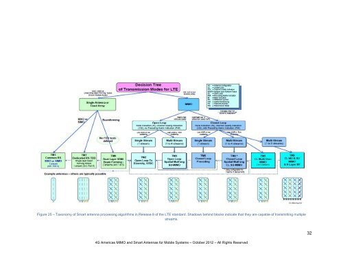
Figure 25 – Taxonomy of <strong>Smart</strong> antenna processing algorithms in Release 8 of the LTE st<strong>and</strong>ard. Shadows behind blocks indicate that they are capable of transmitting multiplestreams.32<strong>4G</strong> <strong>Americas</strong> <strong>MIMO</strong> <strong>and</strong> <strong>Smart</strong> <strong>Antennas</strong> <strong>for</strong> <strong>Mobile</strong> Systems – October 2012 – All Rights Reserved
These transmission modes are implemented through physical antennas described further in Figure 29later in the section.Beyond the single antenna or beam<strong>for</strong>ming array cases diagrammed above, the LTE st<strong>and</strong>ard supportsMultiple Input Multiple Output (<strong>MIMO</strong>) antenna configurations as shown on the right of Figure 25. Thisincludes Single User (SU-<strong>MIMO</strong>) protocols using either open loop or closed loop modes as well astransmit diversity <strong>and</strong> Multi-User <strong>MIMO</strong> (MU-<strong>MIMO</strong>). In the closed loop <strong>MIMO</strong> mode, the terminalsprovide channel feedback to the eNodeB with Channel Quality In<strong>for</strong>mation through CQI, Rank Indications(RI) <strong>and</strong> Precoder Matrix Indications (PMI). These mechanisms enable channel estimation whichimproves the peak data rates, <strong>and</strong> is the most commonly used scheme in current deployments. However,this scheme provides the best per<strong>for</strong>mance only when the channel in<strong>for</strong>mation is accurate <strong>and</strong> whenthere is a rich multipath environment. So closed loop <strong>MIMO</strong> is most appropriate in low mobilityenvironments such as with fixed terminals or those used at pedestrian speeds.In case of high vehicular speeds, Open Loop <strong>MIMO</strong> may be used, but because the channel statein<strong>for</strong>mation is not timely, the PMI is not considered reliable <strong>and</strong> is typically not used. In TDD networks,the channel is reciprocal <strong>and</strong> thus the DL channel can be more accurately known based on the uplinktransmissions from the terminal (the <strong>for</strong>ward link’s multipath channel signature is the same as the reverselink’s – both paths use the same frequency block), so <strong>MIMO</strong> improves TDD networks under wider channelconditions than in FDD networks.One may visualize spatial multiplexing <strong>MIMO</strong> operation as subtracting the strongest received stream fromthe total received signal so that the next strongest signal can be decoded <strong>and</strong> then the next strongest,somewhat like a multi-user detection scheme. However, to solve these simultaneous equations <strong>for</strong>multiple unknowns, the <strong>MIMO</strong> algorithms must have relatively large Signal to Interference plus Noiseratios (SINR), say 15 dB or better. With many users active in a base station’s coverage area, <strong>and</strong>multiple base stations contributing interference to adjacent cells, the SINR is often in the realm of a fewdB. This is particularly true <strong>for</strong> frequency reuse 1 systems, where only users very close to the cell siteexperience SINRs high enough to benefit from spatial multiplexing SU-<strong>MIMO</strong>. Consequently, SU-<strong>MIMO</strong>works to serve the single user (or few users) very well, <strong>and</strong> is primarily used to increase the peak datarates rather than the median data rate in a network operating at full capacity.Angle of Arrival (AoA) beam<strong>for</strong>ming schemes <strong>for</strong>m beams which work well when the base station isclearly above the clutter <strong>and</strong> when the angular spread of the arrival is small,corresponding to users that are well localized in the field of view of the sector;in rural areas, <strong>for</strong> example. To <strong>for</strong>m a beam, one uses co-polarized antennaelements spaced rather closely together, typically λ/2, while the spatialdiversity required of <strong>MIMO</strong> requires either cross-polarized antenna columns orcolumns that are relatively far apart. The farther apart, the more path diversitythey will couple to. This is often about 10 wavelengths (1.5m or 5’ at 2 GHz).This is why most 2G <strong>and</strong> 3G tower sites have two receive antennas located atfar ends of the sector’s plat<strong>for</strong>m as seen in the photo to the right.LTE (<strong>4G</strong>) provides <strong>for</strong> several different variations on Multiple Input Multiple Output (<strong>MIMO</strong>) techniques,from beam<strong>for</strong>ming to <strong>MIMO</strong> or single antenna schemes through selection of one of 9 TransmissionModes (TMs). These Transmission Modes (TMs) classified above in Figure 25 are detailed further in the<strong>4G</strong> <strong>Americas</strong> – <strong>MIMO</strong> <strong>and</strong> <strong>Smart</strong> <strong>Antennas</strong> <strong>for</strong> <strong>Mobile</strong> Broadb<strong>and</strong> Systems - October 2012 - All rights reserved.Page 33/138