MIMO and Smart Antennas for Mobile Broadband ... - 4G Americas
MIMO and Smart Antennas for Mobile Broadband ... - 4G Americas
MIMO and Smart Antennas for Mobile Broadband ... - 4G Americas

You also want an ePaper? Increase the reach of your titles
YUMPU automatically turns print PDFs into web optimized ePapers that Google loves.
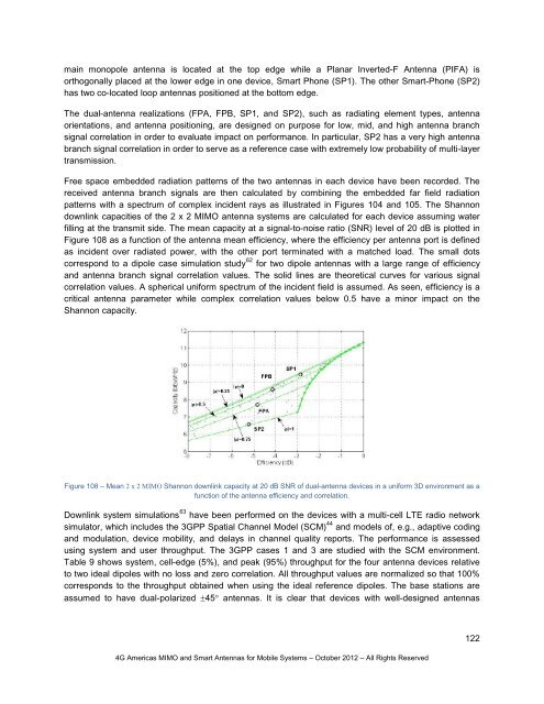
main monopole antenna is located at the top edge while a Planar Inverted-F Antenna (PIFA) isorthogonally placed at the lower edge in one device, <strong>Smart</strong> Phone (SP1). The other <strong>Smart</strong>-Phone (SP2)has two co-located loop antennas positioned at the bottom edge.The dual-antenna realizations (FPA, FPB, SP1, <strong>and</strong> SP2), such as radiating element types, antennaorientations, <strong>and</strong> antenna positioning, are designed on purpose <strong>for</strong> low, mid, <strong>and</strong> high antenna branchsignal correlation in order to evaluate impact on per<strong>for</strong>mance. In particular, SP2 has a very high antennabranch signal correlation in order to serve as a reference case with extremely low probability of multi-layertransmission.Free space embedded radiation patterns of the two antennas in each device have been recorded. Thereceived antenna branch signals are then calculated by combining the embedded far field radiationpatterns with a spectrum of complex incident rays as illustrated in Figures 104 <strong>and</strong> 105. The Shannondownlink capacities of the 2 x 2 <strong>MIMO</strong> antenna systems are calculated <strong>for</strong> each device assuming waterfilling at the transmit side. The mean capacity at a signal-to-noise ratio (SNR) level of 20 dB is plotted inFigure 108 as a function of the antenna mean efficiency, where the efficiency per antenna port is definedas incident over radiated power, with the other port terminated with a matched load. The small dotscorrespond to a dipole case simulation study 62 <strong>for</strong> two dipole antennas with a large range of efficiency<strong>and</strong> antenna branch signal correlation values. The solid lines are theoretical curves <strong>for</strong> various signalcorrelation values. A spherical uni<strong>for</strong>m spectrum of the incident field is assumed. As seen, efficiency is acritical antenna parameter while complex correlation values below 0.5 have a minor impact on theShannon capacity.Figure 108 – Mean 2 x 2 <strong>MIMO</strong> Shannon downlink capacity at 20 dB SNR of dual-antenna devices in a uni<strong>for</strong>m 3D environment as afunction of the antenna efficiency <strong>and</strong> correlation.Downlink system simulations 63 have been per<strong>for</strong>med on the devices with a multi-cell LTE radio networksimulator, which includes the 3GPP Spatial Channel Model (SCM) 44 <strong>and</strong> models of, e.g., adaptive coding<strong>and</strong> modulation, device mobility, <strong>and</strong> delays in channel quality reports. The per<strong>for</strong>mance is assessedusing system <strong>and</strong> user throughput. The 3GPP cases 1 <strong>and</strong> 3 are studied with the SCM environment.Table 9 shows system, cell-edge (5%), <strong>and</strong> peak (95%) throughput <strong>for</strong> the four antenna devices relativeto two ideal dipoles with no loss <strong>and</strong> zero correlation. All throughput values are normalized so that 100%corresponds to the throughput obtained when using the ideal reference dipoles. The base stations areassumed to have dual-polarized ±45° antennas. It is clear that devices with well-designed antennas<strong>4G</strong> <strong>Americas</strong> <strong>MIMO</strong> <strong>and</strong> <strong>Smart</strong> <strong>Antennas</strong> <strong>for</strong> <strong>Mobile</strong> Systems – October 2012 – All Rights Reserved122