

Advanced CAD System for Electromagnetic MEMS Interactive Analysis
Advanced CAD System for Electromagnetic MEMS Interactive Analysis
Advanced CAD System for Electromagnetic MEMS Interactive Analysis

Create successful ePaper yourself
Turn your PDF publications into a flip-book with our unique Google optimized e-Paper software.
The level set equation of evolution is:<br />
Φt + V |∇Φ| = 0<br />
where: Φ = scalar function implicitly representing interface (locus where Φ=0)<br />
V = velocity function normal to the propagating interface incorporating<br />
physics of deposition/etching<br />
In this example we utilize the level set kernel inside of Geodesic (detailed in [32]) with two<br />
velocity functions to simulate wet etching and con<strong>for</strong>mal deposition. In the case of con<strong>for</strong>mal<br />
deposition, we assume a constant normal velocity v = 1.0. In the case of etching we assume a<br />
velocity function which simulates selective isotropic etching.<br />
Inside of Geodesic, the setup required to simulate con<strong>for</strong>mal deposition and isotropic selective<br />
etching is very similar. In the case of deposition, we track the top surface of the device using the<br />
scalar field Φ. In etching, on the other hand, we actually track the boundary of the “air” region<br />
surrounding the device (i.e. the scalar field Φ implicitly represents the surface of the air region).<br />
The reasoning behind the difference is simple. We are only using the zero level set (Φ = 0) to<br />
define a material interface, so we can represent only one material with Φ. Since we want the<br />
ability to do selective etches on multiple materials, we represent the boundary of the “air” region.<br />
In the case of isotropic wet etching, this can be thought of physically as tracking the surface of<br />
the etchant.<br />
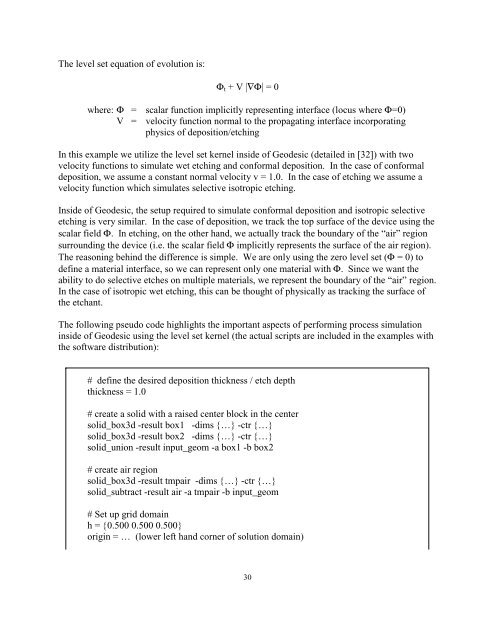
The following pseudo code highlights the important aspects of per<strong>for</strong>ming process simulation<br />
inside of Geodesic using the level set kernel (the actual scripts are included in the examples with<br />
the software distribution):<br />
# define the desired deposition thickness / etch depth<br />
thickness = 1.0<br />
# create a solid with a raised center block in the center<br />
solid_box3d -result box1 -dims {…} -ctr {…}<br />
solid_box3d -result box2 -dims {…} -ctr {…}<br />
solid_union -result input_geom -a box1 -b box2<br />
# create air region<br />
solid_box3d -result tmpair -dims {…} -ctr {…}<br />
solid_subtract -result air -a tmpair -b input_geom<br />
# Set up grid domain<br />
h = {0.500 0.500 0.500}<br />
origin = … (lower left hand corner of solution domain)<br />
30


