User manual 09/2009 - Schneider Electric
User manual 09/2009 - Schneider Electric
User manual 09/2009 - Schneider Electric

You also want an ePaper? Increase the reach of your titles
YUMPU automatically turns print PDFs into web optimized ePapers that Google loves.
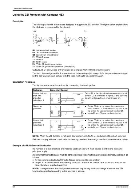
The Protection FunctionUsing the ZSI Function with Compact NSXDescriptionThe Micrologic 5 and 6 trip units are designed to support the ZSI function. The figure below explains howthe pilot wire is connected to the trip unit:Q1Q2Q3Z1Z2Z3Z4Z5Z1Z2Z3Z4Z5Z1Z2Z3Z4Z5Q1 Upstream circuit breakerQ2 Circuit breaker to be wiredQ3 Downstream circuit breakerZ1 ZSI-OUT sourceZ2 ZSI-OUTZ3 ZSI-IN sourceZ4 ZSI-IN ST short time protectionZ5 ZSI-IN GF ground fault protection (Micrologic 6)Outputs Z3, Z4 and Z5 are only available on Compact NSX400/630 circuit breakers.The short time and ground fault protection time delay settings (Micrologic 6) for the protections managedby the ZSI function must comply with the rules relating to time discrimination.Connection PrinciplesThe figures below show the options for connecting devices together:ProtectionConnection DiagramGround fault andshort timeprotection(Micrologic 6)Z1Z2Q1Z3Z4Z5Z1Z2Q2Z3Z4Z5Output Z2 of the trip unit on the downstream circuitbreaker Q2 is connected to inputs Z4 and Z5 of thetrip unit on the upstream circuit breaker Q1.Short timeprotectionZ1Z2Q1Z3Z4Z5Z1Z2Q2Z3Z4Z5• Output Z2 of the trip unit on the downstreamcircuit breaker Q2 is connected to input Z4 of thetrip unit on the upstream circuit breaker Q1.• Inputs Z3 and Z5 must be short-circuited.Ground faultprotection(Micrologic 6)Z1Z2Q1Z3Z4Z5Z1Z2Q2Z3Z4Z5• Output Z2 of the trip unit on the downstreamcircuit breaker Q2 is connected to input Z5 of thetrip unit on the upstream circuit breaker Q1.• Inputs Z4 and Z3 must be short-circuited.NOTE: When the ZSI function is not used downstream, inputs Z3, Z4 and Z5 must be short-circuited.Failure to comply with this principle inhibits setting the short time and ground fault protection time delays.Example of a Multi-Source DistributionIf a number of circuit breakers are installed upstream (as with multi-source distribution), the sameprinciples apply.A downstream circuit breaker must be connected to all the circuit breakers installed directly upstream asfollows:• All the commons (outputs Z1/inputs Z2) are connected to one another.• Output Z2 is connected simultaneously to inputs Z3 and/or Z4 and/or Z5 of all the trip units on thecircuit breakers installed upstream.NOTE: Management of this configuration does not require any additional relays to ensure the ZSIfunction is controlled according to the sources in service.52 LV434104 <strong>09</strong>/20<strong>09</strong>