User manual 09/2009 - Schneider Electric
User manual 09/2009 - Schneider Electric
User manual 09/2009 - Schneider Electric

Create successful ePaper yourself
Turn your PDF publications into a flip-book with our unique Google optimized e-Paper software.
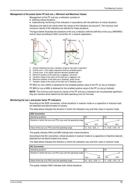
The Metering FunctionManagement of the power factor PF and cos ϕ: Minimum and Maximum ValuesManagement of the PF and cos ϕ indicators consists of:• Defining critical situations• Implementing monitoring of the indicators in accordance with the definition of critical situationsSituations are said to be critical when the values of the indicators are around 0. The minimum andmaximum values of the indicators are defined for these situations.The figure below illustrates the variations of the cos ϕ indicator (with the definition of the cos ϕ MIN/MAX)and its value according to IEEE convention for a receiver application:- 0Q131- 0Q1MIN cos 41+02Q4-1+1cos + 0Q41 Arrows indicating the cos ϕ variation range for the load in operation2 Critical zone + 0 for highly capacitive devices (shaded green)3 Critical zone - 0 for highly inductive devices (shaded red)4 Minimum position of the load cos ϕ (lagging): red arrow5 Variation range of the value of the load cos ϕ (lagging): red6 Maximum position of the load cos ϕ (leading): green arrow7 Variation range of the value of the load cos ϕ (leading): green657PF MAX (or cos ϕ MAX) is obtained for the smallest positive value of the PF (or cos ϕ) indicator.PF MIN (or cos ϕ MIN) is obtained for the smallest positive value of the PF (or cos ϕ) indicator.NOTE: The minimum and maximum values of the PF and cos ϕ indicators are not physically significant:they are markers which determine the ideal operating zone for the load.-1+1cos MAX cos Monitoring the cos ϕ and power factor PF indicatorsAccording to the IEEE convention, critical situations in receiver mode on a capacitive or inductive loadare detected and discriminated (2 values).The table below indicates the direction in which the indicators vary and their value in receiver mode.IEEE ConventionOperating quadrant Q1 Q4Direction in which the cos ϕ (or PFs) vary over the operating rangeValue of the cos ϕ (or PFs) over the operating range -0...-0,3...-0,8...-1 +1...+0,8...+0,4...+0The quality indicator MAX and MIN indicate both critical situations.According to the IEC convention, critical situations in receiver mode on a capacitive or inductive load aredetected but not discriminated (one value).The table below indicates the direction in which the indicators vary and their value in receiver mode.IEC ConventionOperating quadrant Q1 Q4Direction in which the cos ϕ (or PFs) vary over the operating rangeMAX MIN MIN MAXValue of the cos ϕ (or PFs) over the operating range +0...+0,3...+0,8...+1 +1...+0,8...+0,4...+0The quality indicator MAX indicates both critical situations.MIN MAX MIN MAXLV434104 <strong>09</strong>/20<strong>09</strong> 93