1535 Relative Humidity Transmitter - Novatech Controls
1535 Relative Humidity Transmitter - Novatech Controls
1535 Relative Humidity Transmitter - Novatech Controls
Create successful ePaper yourself
Turn your PDF publications into a flip-book with our unique Google optimized e-Paper software.
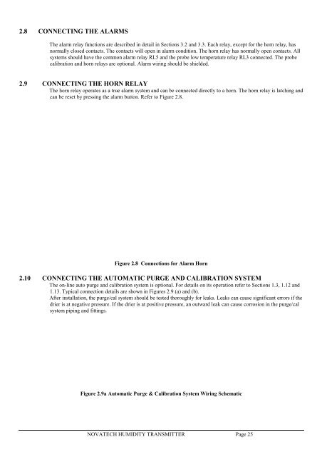
!2.8 CONNECTING THE ALARMSThe alarm relay functions are described in detail in Sections 3.2 and 3.3. Each relay, except for the horn relay, hasnormally closed contacts. The contacts will open in alarm condition. The horn relay has normally open contacts. Allsystems should have the common alarm relay RL5 and the probe low temperature relay RL3 connected. The probecalibration and horn relays are optional. Alarm wiring should be shielded.2.9 CONNECTING THE HORN RELAYThe horn relay operates as a true alarm system and can be connected directly to a horn. The horn relay is latching andcan be reset by pressing the alarm button. Refer to Figure 2.8.Figure 2.8 Connections for Alarm Horn2.10 CONNECTING THE AUTOMATIC PURGE AND CALIBRATION SYSTEMThe on-line auto purge and calibration system is optional. For details on its operation refer to Sections 1.3, 1.12 and1.13. Typical connection details are shown in Figures 2.9 (a) and (b).After installation, the purge/cal system should be tested thoroughly for leaks. Leaks can cause significant errors if thedrier is at negative pressure. If the drier is at positive pressure, an outward leak can cause corrosion in the purge/calsystem piping and fittings.Figure 2.9a Automatic Purge & Calibration System Wiring SchematicNOVATECH HUMIDITY TRANSMITTER Page 25


