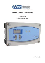
1535 Relative Humidity Transmitter - Novatech Controls
1535 Relative Humidity Transmitter - Novatech Controls
1535 Relative Humidity Transmitter - Novatech Controls
Create successful ePaper yourself
Turn your PDF publications into a flip-book with our unique Google optimized e-Paper software.
!If the probe tests reveal less than 2 mV offset and a good impedance reading, the next step is to apply a calibrationgas. The calibration gas should be inserted in the calibration port. With the calibration gas flowing, the probe shoulddevelop an EMF according to the tables in Appendix 2. If the EMF reading is low, then there may be insufficientcalibration gas flow. Increase the calibration gas until the reading is correct. An excessive calibration gas flow willcause cooling on one surface of the sensor, giving temperature differential errors on the sensor.The sensor accuracy should be within 0.5 mV with the same offset which was measured with air on both sides of thesensor. If the probe EMF is not within this tolerance, then the electrodes will need to be refurbished.As an alternative, using the reference gas port, the calibration gas can be inserted into the inside of the sensor. Thisrequires a lower flow rate, and thus lower usage of calibration gas. The flow rate should be similar to that of thereference gas which should be removed for internal calibration. The probe EMF reading will be identical butnegative in polarity. A small flow of air should be flowing over the outside of the sensor, when testing in this way.Occasionally a sensor can develop offset with a polluted electrode caused by contaminants in the flue gas stream. Inthis case, the old electrode material must be completely cleaned off before re-applying the fresh electrode material.Again, return the probe or sensor to an accredited service organisation.5.11 SENSOR IMPEDANCEIf the sensor impedance is found to be high in the test described in Section 5.10, it may be necessary to move theinner electrode slightly to re-establish contact. This is achieved by gently pulling the four bore ceramic tube againstits spring loading for approximately 1 mm and releasing. This procedure is normally only required with a probewhich has been sitting cold for many months.With some probes you may view the sensor electrode from outside the outer sheath. The electrode material should beeither grey or green and should fully cover the end of the sensor. If any cream coloured ceramic material is visible atthe sensor end, then the electrode has been degraded and will require refurbishment.5.12 PROBE THERMOCOUPLEThe transmitter has an alarm function which will advise the operator of an open circuit probe thermocouple,however, bench testing can be performed by simply measuring the thermocouple continuity. If the thermocouplerequires replacement, care should be taken not to physically damage the inner electrode material during removal andreplacement of the thermocouple and insulator.5.13 HEATER FAILUREA heater failure will cause a ‘HEATER FAILURE’ alarm. Heaters can be tested from the probe head with acontinuity test.The heater impedance should be approximately 110_. Should the heater be open circuit, contact an accreditedservice agent for replacement.NOVATECH HUMIDITY TRANSMITTER Page 51


