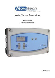
1535 Relative Humidity Transmitter - Novatech Controls
1535 Relative Humidity Transmitter - Novatech Controls
1535 Relative Humidity Transmitter - Novatech Controls
You also want an ePaper? Increase the reach of your titles
YUMPU automatically turns print PDFs into web optimized ePapers that Google loves.
!2.15 REFERENCE GAS FLOW SWITCHEnsure that the reference gas is flowing and that the reference gas flow switch is closed by pressing the alarm buttonto ensure a ‘REF AIR FAIL’ alarm is not occurring.2.16 COMMISSIONING–MAINTENANCE MODESwitch the mode switch to ‘MAINT’. Enter the date and time. If the transmitter has performed a ‘COLD START’,the reference voltage and D/A calibrations will have to be performed. If a ‘COLD START’ has been performed or anew probe installed then the probe offset will need to be set. Refer to Section 5 for full details on calibration. Referto Section 5.5.10 and 2.21 for details on probe offset calibration.2.17 COMMISSIONING–SET UP MODESwitch the mode switch to ‘SET-UP’ and enter all set up functions as listed in Section 4.2.18 RUN MODESwitch the mode switch to ‘RUN’. The upper line of the display will now read ‘% RELATIVE HUMIDITY’ or ‘%WATER VAPOUR’. The probe temperature can be checked on the lower line of the display. % <strong>Relative</strong> <strong>Humidity</strong>or % Water Vapour readings are not valid when the probe is below 650°C.2.19 HEATER BYPASS SWITCH (DIRECT FIRED DRYERS ONLY)In indirectly heated dryers, leave the heater by-pass switch in the ‘off’ position and RL7 permanently linked to themains supply. See Section 2.2In directly heated dryers, heated probes should have their heater supply interlocked with RL 7. If the driercombustion is off, then power will not be supplied to the heater.With direct fired dryers, to commission an oxygen probe when the main burner is turned off, switch power off thetransmitter, remove the probe from the mounting point and connect the lead with the probe laying on a metal orceramic surface external to the flue and capable of withstanding 750°C.Re-apply power to the transmitter and press the burner by-pass switch into the ‘down’ position. This will applypower to the probe heater even when the plant is not running. The probe offset can now be set and calibrationchecked with appropriate calibration gases (typically 2 % oxygen in nitrogen).Ensure that the burner by-pass switch and the power are turned off before the probe is re-installed. An alarm willoccur if the burner by-pass switch is turned on (down) during normal operation.2.20 CHECKING THE ALARMSIf any alarms are present the alarm LED should be lit, either flashing or steady. To interpret the alarms, repeatedlypress the alarm button until all alarm functions have been displayed. Rectify the cause of each alarm until no furtheralarms appear on the display. For details on the operation of the alarm button and the alarm functions refer to Section3.NOVATECH HUMIDITY TRANSMITTER Page 29


