1535 Relative Humidity Transmitter - Novatech Controls
1535 Relative Humidity Transmitter - Novatech Controls
1535 Relative Humidity Transmitter - Novatech Controls
You also want an ePaper? Increase the reach of your titles
YUMPU automatically turns print PDFs into web optimized ePapers that Google loves.
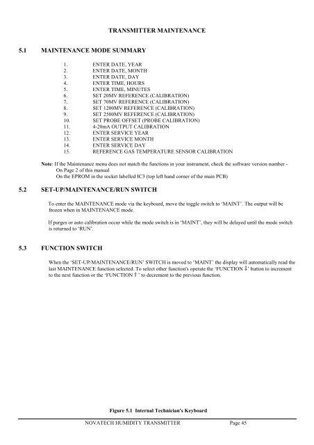
!TRANSMITTER MAINTENANCE5.1 MAINTENANCE MODE SUMMARY1. ENTER DATE, YEAR2. ENTER DATE, MONTH3. ENTER DATE, DAY4. ENTER TIME, HOURS5. ENTER TIME, MINUTES6. SET 20MV REFERENCE (CALIBRATION)7. SET 70MV REFERENCE (CALIBRATION)8. SET 1200MV REFERENCE (CALIBRATION)9. SET 2500MV REFERENCE (CALIBRATION)10. SET PROBE OFFSET (PROBE CALIBRATION)11. 4-20mA OUTPUT CALIBRATION12. ENTER SERVICE YEAR13. ENTER SERVICE MONTH14. ENTER SERVICE DAY15. REFERENCE GAS TEMPERATURE SENSOR CALIBRATIONNote: If the Maintenance menu does not match the functions in your instrument, check the software version number -On Page 2 of this manualOn the EPROM in the socket labelled IC3 (top left hand corner of the main PCB)5.2 SET-UP/MAINTENANCE/RUN SWITCHTo enter the MAINTENANCE mode via the keyboard, move the toggle switch to ‘MAINT’. The output will befrozen when in MAINTENANCE mode.If purges or auto calibration occur while the mode switch is in ‘MAINT’, they will be delayed until the mode switchis returned to ‘RUN’.5.3 FUNCTION SWITCHWhen the ‘SET-UP/MAINTENANCE/RUN’ SWITCH is moved to ‘MAINT’ the display will automatically read thelast MAINTENANCE function selected. To select other function's operate the ‘FUNCTION ⇓’ button to incrementto the next function or the ‘FUNCTION ⇑ ’ to decrement to the previous function.Figure 5.1 Internal Technician's KeyboardNOVATECH HUMIDITY TRANSMITTER Page 45


