Evaluation of Greenhouse Gas Emissions from Septic ... - Geoflow
Evaluation of Greenhouse Gas Emissions from Septic ... - Geoflow
Evaluation of Greenhouse Gas Emissions from Septic ... - Geoflow

Create successful ePaper yourself
Turn your PDF publications into a flip-book with our unique Google optimized e-Paper software.
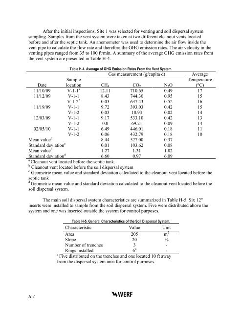
After the initial inspections, Site 1 was selected for venting and soil dispersal systemsampling. Samples <strong>from</strong> the vent system were taken at two different cleanout vents locatedbefore and after the septic tank. An anemometer was used to determine the air flow inside thevent pipe to calculate the flow rate and therefore the GHG emission rates. The air velocity in theventing pipes ranged <strong>from</strong> 35 to 100 ft/min. A summary <strong>of</strong> the average GHG emission rates <strong>from</strong>the vent system are presented in Table H-4.Table H-4. Average <strong>of</strong> GHG Emission Rates From the Vent System.<strong>Gas</strong> measurement (g/capita·d)AverageTemperature(°C)DateSamplelocation CH 4 CO 2 N 2 O11/10/09 V-1-1 a 12.11 710.65 0.49 1711/12/09 V-1-1 8.43 744.30 0.95 15V-1-2 b 0.03 637.43 0.52 1611/19/09 V-1-1 9.72 393.03 0.42 15V-1-2 0.03 10.93 0.02 1412/03/09 V-1-1 9.17 533.10 0.42 13V-1-2 0.0 69.21 0.09 1402/05/10 V-1-1 6.49 446.01 0.18 11V-1-2 0.06 432.79 0.18 10Mean value c 8.44 527.00 0.37Standard deviation c 0.01 103.62 0.08Mean value d 1.27 1.31 1.82Standard deviation d 6.60 0.97 6.09aCleanout vent located before the septic tank.b Cleanout vent located before the soil dispersal systemc Geometric mean value and standard deviation calculated to the cleanout vent located before theseptic tankdGeometric mean value and standard deviation calculated to the cleanout vent located before thesoil dispersal system.The main soil dispersal system characteristics are summarized in Table H-5. Six 12"inserts were installed to sample <strong>from</strong> the soil dispersal system. Five were distributed above thesystem and one was inserted outside the system for control purposes.Table H-5. General Characteristics <strong>of</strong> the Soil Dispersal System.Characteristic Value UnitArea 205 m 2Slope 20 %Number <strong>of</strong> trenches 3 -Rings installed 6 a -aFive distributed on the trenches and one located 10 ft away<strong>from</strong> the dispersal system area for control purposes.H-4