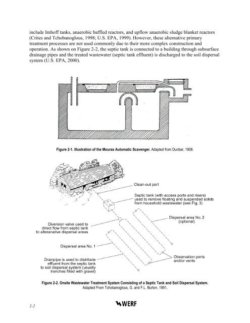
CHAPTER 2.0LITERATURE REVIEWTo assess the potential for the release <strong>of</strong> greenhouse gases <strong>from</strong> septic tanks, thecharacteristics <strong>of</strong> onsite systems are reviewed in this chapter. The subjects considered in thisreview include an overview <strong>of</strong> the development <strong>of</strong> septic tank systems, the physicalcharacteristics and operation <strong>of</strong> septic tanks, the fundamentals <strong>of</strong> the anaerobic processesoccurring in septic tanks, and the information that exists on the emissions <strong>from</strong> septic tanks andother wastewater sources.2.1 Overview <strong>of</strong> <strong>Septic</strong> Tank SystemsThe septic tank is one <strong>of</strong> the oldest units available for the primary treatment <strong>of</strong>wastewater <strong>from</strong> decentralized sources. The historical background <strong>of</strong> the septic tank and itsimportance in decentralized wastewater treatment systems are discussed in this section. Anintroductory overview <strong>of</strong> gaseous emissions <strong>from</strong> septic tanks is also presented along with a briefdescription <strong>of</strong> venting systems and the soil absorption field.2.1.1 Historical BackgroundWastewater <strong>from</strong> individual buildings and small communities is <strong>of</strong>ten managed usingonsite wastewater systems when a centralized wastewater collection system is not available.Nearly all onsite wastewater systems incorporate a septic tank for primary treatment <strong>of</strong> influentwastewater (Crites and Tchobanoglous, 1998). A septic tank is a buried, watertight tank designedand constructed to receive and partially treat raw wastewater (U.S. PHS, 1957; U.S. EPA, 2009).It is estimated that about 25 million septic tanks are currently in use in the United States (U.S.EPA, 2002).<strong>Septic</strong> tanks were first reported as wastewater treatment systems in the 1860s in France.The Fosse Mouras automatic scavenger was patented in 1881, based on the work <strong>of</strong> AbbeMoigno and Louis M. Mouras (Dunbar, 1908; Winneberger, 1984). An illustration <strong>of</strong> the FosseMouras septic treatment process is presented on Figure 2-1. The process configuration since thattime remains almost unchanged when compared to modern septic systems (Crites andTchobanoglous, 1998).2.1.2 Onsite Wastewater Treatment SystemsThe key functions <strong>of</strong> the septic tank are to separate and retain settleable solids (sludge) andfloatables (scum) <strong>from</strong> the incoming wastewater. Subsequently, the treated wastewater isdischarged typically into a soil dispersal system, also known as a leach field. The captured solidsare retained in the septic tank and undergo a passive (naturally occurring and uncontrolled)anaerobic digestion (Tchobanoglous and Schroeder, 1985). The combination <strong>of</strong> septic tank andleach field, shown on Figure 2-2, is the most commonly used onsite wastewater treatmentsystem. Other types <strong>of</strong> primary treatment processes used in decentralized wastewater systems<strong>Evaluation</strong> <strong>of</strong> <strong>Greenhouse</strong> <strong>Gas</strong> <strong>Emissions</strong> <strong>from</strong> <strong>Septic</strong> Systems 2-1
include Imh<strong>of</strong>f tanks, anaerobic baffled reactors, and upflow anaerobic sludge blanket reactors(Crites and Tchobanoglous, 1998; U.S. EPA, 1999). However, these alternative primarytreatment processes are not used commonly due to their more complex construction andoperation. As shown on Figure 2-2, the septic tank is connected to a building through subsurfacedrainage pipes and the treated wastewater (septic tank effluent) is discharged to the soil dispersalsystem (U.S. EPA, 2000).Figure 2-1. Illustration <strong>of</strong> the Mouras Automatic Scavenger. Adapted <strong>from</strong> Dunbar, 1908.Figure 2-2. Onsite Wastewater Treatment System Consisting <strong>of</strong> a <strong>Septic</strong> Tank and Soil Dispersal System.Adapted From Tchobanoglous, G. and F.L. Burton, 1991.2-2
- Page 1 and 2: D e c e n t r a l i z e dEvaluation
- Page 3 and 4: The Water Environment Research Foun
- Page 5 and 6: ABSTRACT AND BENEFITSAbstract:This
- Page 7 and 8: 3.1.2 Flux Chamber Inserts for Sept
- Page 9 and 10: LIST OF TABLESES-1 Summary of Metha
- Page 11 and 12: 3-7 Use of Flux Chamber in the Soil
- Page 13 and 14: Evaluation of Greenhouse Gas Emissi
- Page 15 and 16: tank is converted anaerobically. Fu
- Page 17 and 18: RecommendationsBased on the finding
- Page 19: ♦♦Collection of gas samples fro
- Page 23 and 24: 2.2 Septic Tank CharacteristicsSept
- Page 25 and 26: 2.2.3 General Conversion Processes
- Page 27 and 28: increase in thickness with daily so
- Page 29 and 30: environmental damage and/or health
- Page 31 and 32: Figure 2-6. The Intermediate Steps
- Page 33 and 34: In anaerobic reactors, the alkalini
- Page 35 and 36: epresentative concentrations. Inhib
- Page 37 and 38: 2.4 Gas Emissions from Septic Syste
- Page 39 and 40: Figure 2-9. Flux Chamber Designed b
- Page 41 and 42: due to settling and anaerobic diges
- Page 43 and 44: total methane production value of 1
- Page 45 and 46: 2-26
- Page 47 and 48: The main body of the flux chamber w
- Page 49 and 50: 3.1.3 Flux Chamber Design for Use i
- Page 51 and 52: 3.2 Sampling ProtocolsThe three pri
- Page 53 and 54: 3.2.3 Sampling Method for Vent Syst
- Page 55 and 56: 3.3 Gas AnalysisThe gas samples wer
- Page 57 and 58: ppm (raw data from laboratory) were
- Page 59 and 60: gal. Sites 5, 6, and 7 were the onl
- Page 61 and 62: Table 4-2. Continued from previous
- Page 63 and 64: Three of the septic tanks that appe
- Page 65 and 66: steeper than that for the rest of t
- Page 67 and 68: espectively, and for methane were 4
- Page 69 and 70: oth before and after the septic tan
- Page 71 and 72:
noted that in this approach it is a
- Page 73 and 74:
The septic tank effluent CO 2 equiv
- Page 75 and 76:
(a)(b)Figure 5-9. Gas Emission Rate
- Page 77 and 78:
Figure 5-11. Emission Rates from Si
- Page 79 and 80:
(a)(b)Figure 5-13. Views of the Eff
- Page 81 and 82:
It is important to note that the U.
- Page 83 and 84:
♦ Methane generated during the an
- Page 85 and 86:
A-2
- Page 87 and 88:
B. Based on COD Loading1. Determine
- Page 89 and 90:
C-2
- Page 91 and 92:
2. First row of Table 23 from Sasse
- Page 93 and 94:
Biogas production = (COD inflow - C
- Page 95 and 96:
E-2
- Page 97 and 98:
SAMPLING FROM SOIL SURFACEDate:Hour
- Page 99 and 100:
F-4
- Page 101 and 102:
G-2
- Page 103 and 104:
DateSamplelocationGas measurement (
- Page 105 and 106:
After the initial inspections, Site
- Page 107 and 108:
H-2 Site 2The scum layer in the fir
- Page 109 and 110:
Table H-10. GHG Emission Rates From
- Page 111 and 112:
Table H-14. Summary of the Water Qu
- Page 113 and 114:
Table H-18. Summary of the Water Qu
- Page 115 and 116:
Table H-22. GHG Emission Rates from
- Page 117 and 118:
Sample Gas measurement (g/capita·d
- Page 119 and 120:
H-9 Summary of ResultsA summary of
- Page 121 and 122:
I-2
- Page 123 and 124:
Treatment in Decentralized Wastewat
- Page 125 and 126:
Philip, H., S. Maunoir, A. Rambaud,
- Page 127 and 128:
Winfrey, M.R. and J.G. Zeikus (1977
- Page 129 and 130:
Fort Worth, City ofHouston, City of
- Page 132:
W E R F P r o d u c t O r d e r F o